


13
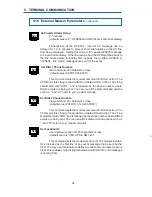
External IID Connector
The external IID connector provides an interface for the optional desktop
Intelligent Interface Device (IID). This allows the CFR to be remotely monitored
and controlled from up to 2,000 feet away. The port uses a proprietary RS-485
protocol and has the following pin out:
1: +12V DC (unreg)
4: RS-485 Negative
2: +12V DC (unreg)
5: GND
2. FEATURES
2.5
Communication / Interface Options
, continued
External Alarms Connector
The external alarms connector provides two contact closures to indicate
LINE FAIL and LOW BATTERY alarms.
EPO (Emergency Power OFF) Switch
(Factory Installed Option)
Pins 7 and 8 of the ALARM INTERFACE connector provide EMERGENCY
POWER OFF contacts. A switch contact can be hard-wired to the UPS to
completely shut down the system in the event of an emergency, such as a
fire.
In an emergency, the switch must be depressed (shorted) for at least 1.5
seconds. The UPS will shut down approximately 2 seconds after the signal is
recognized. The switch, connected to pins 7 and 8, must be electrically isolated
(up to 1500 VAC isolation is recommended). A system shut down in this manner
will open the BATTERY circuit breaker.
CAUTION: When the EPO switch is activated, the AC LINE connected to
the UPS input may still be energized. To completely remove the power
from the building, the MAIN AC LINE breaker in the building must be
switched OFF. Consult your national and local electrical codes for further
information.
Pin 1
Fig 7.
External IID connector Pin out: (MMJ Connector, offset key)
60
5.13 Event Descriptions (Alarms)
,
continued
Several alarms can be triggered during the same event. If there is a loss of
AC line voltage, for example, the UPS may detect a glitch, low frequency and
blackout.
Low Battery Warning (LO_BAT_WARN) - The batteries are near the end of
their useful charge. If AC line power is not restored within a short period of time, output
power will be lost. All systems should be shutdown immediately to prevent loss of
data.
Low Battery Shutdown (LO_BAT_SHTDWN) - To prevent an over-discharge
condition of the batteries, the unit has shutdown. Output power is terminated in this
condition.
Battery Voltage High (BAT_VOLT_HI) - The charging voltage is higher than
the threshold setting for the batteries. This could be the result of a defective charger,
improper external battery connections, or defective batteries. Service the unit or batteries
to correct condition.
NOTE: This condition activates the SERVICE alarm, along with an audible
alarm which can be cleared by pressing the ALARM OFF or MUTE key.
Failed Self-Test (FAIL_SELF_TEST) - The unit could not maintain output
power while in the self-test mode. Check the batteries and circuit breakers.
NOTE: This condition activates the SERVICE alarm, along with an audible
alarm which can be cleared by pressing the ALARM OFF or MUTE key.
Battery Fault (BATT_FLT) - The battery charger is not able to supply the
proper amount of current or voltage to the batteries. This condition usually indicates
that the batteries are not connected or the BATTERY circuit breaker is switched OFF.
Glitch (GLITCH) - A glitch is a fast, low amplitude line disturbance where the
input voltage drops momentarily (less than 8 ms). * *
Spike (SPIKE) - A spike is a fast, high amplitude line disturbance where the
input voltage rises momentarily (less than 8 ms). * *
Sag (SAG) - A sag is a slow, low amplitude line disturbance where the input
voltage decreases for 8 - 40 ms. * *
Surge (SURGE) - A surge is a slow, high amplitude line disturbance where the
input voltage increases for 8 - 40 ms. * *
Brownout (BROWNOUT) - A brownout is a slow, low amplitude line disturbance
where the input voltage decreases for a long period of time (greater than 16 ms). * *
Slow Surge (SLOW_SURGE) - A brownout high (high overvoltage) is a slow,
high amplitude line disturbance where the input voltage increases for a long period of
time (greater than 16 ms). * *
5. RS-232 TERMINAL COMMUNICATION
* * Indicates events that cause the UPS to operate in “LINE FAILURE” mode.


