background image

GLD 

Chrome Edition

 User Guide


22 

 AP9989 iss.1 


Working with the 

Mix

 on the fader strips


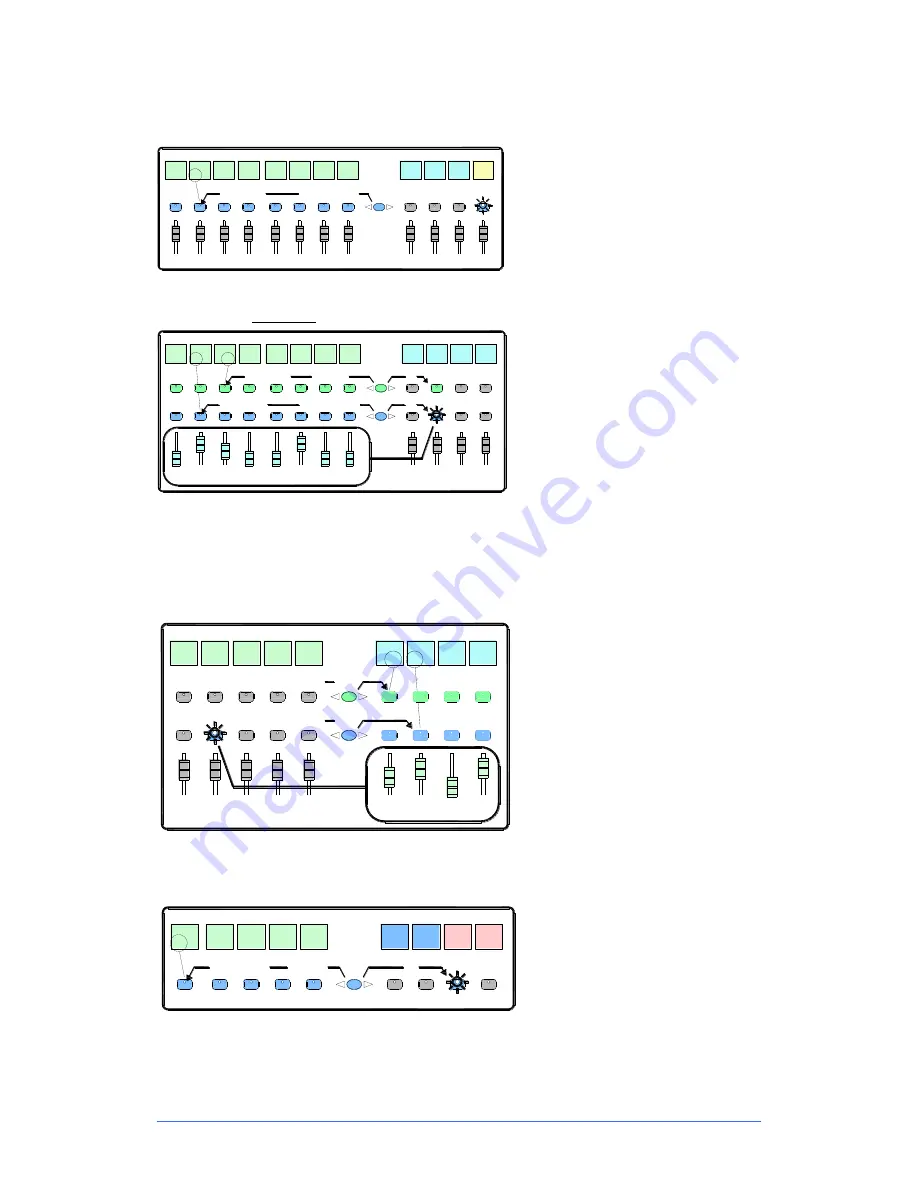
Press a Main Mix master strip 

Mix

 key. 

This is the normal mixing mode.  The Input strips 
present the channel faders.  The Master strips 
present the master mix faders. 

Hold down the 

Assign

 key and press channel 

Mix

 keys to assign or de-assign them from the 

main mix.  Current ON status is displayed on the 
lower part of the strip LCDs. 


Mix

Aux3

Mix

IP 1

IP 2

IP 3

IP 4

IP 5

IP 6

IP 7

IP 8

Aux1

Aux2

LR

Channel faders

Master faders

+ press Mix

ON

Normal mix mode (FOH)

Assign Routing

Main

Mix

active

hold

down

Press a Mix master strip 

Mix

 key. 

Use this to work with Aux and FX sends.  The 
Input strips change to present all the send levels 
to the selected mix.  The Master strips present 
the master mix faders. 

Hold down the 

Assign

 key and press channel 

Mix

 keys to assign or de-assign them from the 

selected mix. 

Hold down the 

Pre/Post 

key and press channel 

Sel

 keys to toggle each source pre or post fader. 

Current PRE status is displayed on the lower part 
of the channel strip LCDs. 

You can quickly set 

all 

assignments on or off, or 

all sources pre or post fader by pressing the 
Master strip 

Mix

 or 

Sel

 key instead of a channel 

key as described above. 


All sends to one master

Master faders

Aux3

Sel

Mix

IP 1

IP 2

IP 3

IP 4

IP 5

IP 6

IP 7

IP 8

Aux1

Aux2

+ press Mix

Assign Routing

ON

all

+ press Sel

Pre/Post

PRE

Master 

Mix


all

Aux4

view

Access Aux, FX, Matrix mix on faders

hold

down

Press an Input Channel strip 

Mix

 key. 

Use this to work with Aux and FX sends.  The Input 
strips remain as Channel Faders.  The Master 
strips change to present all sends from the 
selected channel. 

Hold down the 

Assign

 key and press master 

Mix


keys to assign or de-assign the channel from each 
mix. 

Hold down the 

Pre/Post 

key and press master 

Sel


keys to toggle the channel pre or post fader to each 
mix. Current status is displayed on the master strip 
LCDs. 

IP 6

IP 7

IP 8

Aux1

Aux2

ON

PRE

Channel faders

Aux3

Sel

Mix

Channel

Mix

Assign Routing

Pre/Post


Aux4

All sends from one input

view

IP 5

IP 4

hold

down

Press a Group Master strip 

Mix

 key. 

Use this to assign channels to the Audio and DCA 
groups.  The Input and Master faders are not 
affected. 

Hold down the 

Assign

 key and press channel 

Mix


keys to assign or de-assign the channels from the 
group. 

IP 4

IP 5

IP 6

IP 7

IP 8

Grp1

Grp2

+ press Mix

all

DCA

Mix

DCA and Audio Group assign

Assign

DCA2

ON

DCA

1

hold

down

Содержание GLD CHROME EDITION

Страница 1: ...DIGITAL MIXING SYSTEM User Guide Check the Allen Heath web site for the latest version available Publication AP9989 Issue 1...

Страница 2: ...terms of this warranty may be fulfilled with functionally equivalent service exchange units This warranty is not transferable This warranty will be the purchaser s sole and exclusive remedy and neithe...

Страница 3: ...vailable online and the on screen Help Manual available on the mixer Refer to the Allen Heath website for additional downloads resources knowledgebase and technical support General precautions To prev...

Страница 4: ...Mixer controls 10 GLD Chrome Mixer rear connectors 11 Connect and power up 12 GLD Editor iPad apps and wireless router 13 Recall a Template Show as a starting point 15 Template Show Settings 16 A few...

Страница 5: ...dition to the mixer rear connections This gives you a distributed audio system with convenient Cat5 digital snake based on the proprietary Allen Heath dSNAKE protocol AR2412 24 Mic Line in 12 Line out...

Страница 6: ...ake up to 120m 400 length High grade 1dB step recallable mic line preamps 48 channels into 30 buses into 20 mix outputs assignable mono stereo Group Aux FX Main Matrix 8 stereo RackFX engines with ded...

Страница 7: ...PANDER port on the GLD mixer can only be connected to an AR84 The diagram below shows the interconnection and socket numbering of the system Each socket is identified by the device and socket number A...

Страница 8: ...mic inputs GLD AR2412 2x AR84 Expanded AR system 48 in 30 out 40 remote mic inputs GLD AB168 Rugged digital stage box 24 in 18 out 16 remote mic inputs GLD 2x AB168 Two digital stage boxes 40 in 26 ou...

Страница 9: ...g through the GLD mixer The AudioRacks provide inputs as shown in the Remote Inputs box and outputs as shown in the Remote Outputs box These signals connect to the GLD via the dSNAKE or EXPANDER ports...

Страница 10: ...screen Input overrides output mix PAFL Strip LCD display to show channel status information and user defined Name and Colour Press to Talk Talkback source and destination is assigned using the Setup A...

Страница 11: ...t and On Off switch Surface audio outputs 6 analogue and 4 digital outputs 4 XLR line out skt 21 24 1 stereo RCA pair skt 25 26 1 SPDIF 2 channel digital out skt 27 28 1 AES 2 channel digital out skt...

Страница 12: ...lash steadily showing that the link between the mixer and racks is established The mixer Audio Sync LOCK indicator lights Finally the AudioRack Ready indicators light and you will hear a click as the...

Страница 13: ...of suitably high performance quality and reliability For best performance we recommend you choose a dual band wireless router with auto channel selection Use the more recent 5GHz band in places where...

Страница 14: ...age If you want you can change the SSID to help you identify it alongside other wireless networks in the area After setup the wireless router can be connected to the Network socket on the rear of the...

Страница 15: ...how is already loaded when the GLD is shipped from the factory This is Template1 LR You can load a different Template as your starting point if you wish To load a Template Show Go to the Setup Memory...

Страница 16: ...eset GLD 80 Template default Scene 2 and 500 backup Reset GLD 112 Template default Scene 498 Reset MIDI Strips restores default MIDI Strip message settings The Template Show Board Reset Scene Each Tem...

Страница 17: ...ls of groups of signals such as drums vocals and effects 6 DCA masters are assigned to the faders You can assign more as required Talkback using mic socket 44 Rear panel mic input 44 is patched as the...

Страница 18: ...number Direct Out Post Delay Pre fade Post Mute Default Pan Monitor Out ME 1 mode PEQ 20 20kHz Curve Fill On Scene Edit Confirmation On SoftKeys are Scene Safe 1 9 17 L A1 A5 R A2 A6 M A3 A1 A4 A1 2 1...

Страница 19: ...a monitor level Tabs to open one of the 4 custom meter pages or the RTA real time analyser display The RTA follows the PAFL signal Custom meters are assigned using the Meters screen Displays system i...

Страница 20: ...nment to the currently selected Mix User defined backlight Colour Strip Rotary setting Assignment Mix type Pre Post fader setting User defined channel Name Touch the top left Name box in the Processin...

Страница 21: ...sing and check signal activity Note GLD meters are fast response digital absolute peak meters This ensures you keep control and avoid digital clipping of signals including those with very fast dynamic...

Страница 22: ...all sources pre or post fader by pressing the Master strip Mix or Sel key instead of a channel key as described above All sends to one master Master faders Aux3 Sel Mix IP 1 IP 2 IP 3 IP 4 IP 5 IP 6...

Страница 23: ...announcement while a band sound check is recalled Refer to the GLD Touch Screen Reference Guide for more information on using Scenes and the other functions accessed via the screen Display the full l...

Страница 24: ...as a User Scene set Touch to open the keypad and Apply a name for the selected User Touch to set or change the password This is entered twice to avoid errors You can add a comment to display here and...

Страница 25: ...e IO Surface screen For example record the main mix a stereo group aux or matrix or two independent mono signals USB recording is fed from Stereo Matrix1 in the factory Template Shows Check recording...

Страница 26: ...Open up the zip file you have just downloaded Extract all files to the root directory of your USB key Once the extraction is complete check that a new Firmware directory has appeared under the AllenH...

Страница 27: ...n do this by clicking on the small eject icon by the USB key in Finder Step5 Plug the key into a USB port on the GLD Plug your USB key into either one of the USB ports on the GLD 80 Go to the Setup Ut...

Страница 28: ...t USB Playback 2 channel WAV FLAC 44 1 48kHz USB Record 2 channel 48kHz 16bit WAV I O Port 64 channel bi directional Card Options A H ACE MADI Dante ES Waves MMO Operating Temperature 0 deg C to 35 de...

Страница 29: ...0 240V AC 50 60Hz 110W max GLD AR2412 100 240V AC 50 60Hz 70W max GLD AR84 100 240V AC 50 60Hz 20W max Dimensions and Weights GLD 80 Mixer Width x Depth x Height Unpacked 730 x 577 x 159mm 28 7 x 22 7...

Страница 30: ...function Assignment Mix type Pre Post send Stereo Channel assignment to current Mix See where Input and Master Faders are by pressing Layer keys A B C D and reading the displays To change the socket...

Страница 31: ...GLD Chrome Edition User Guide 31 AP9989 iss 1...

Страница 32: ...GLD Chrome Edition User Guide 32 AP9989 iss 1...

Отзывы: