


FS3 Frame Synchronizer/Converter v1.1r1 66 www.aja.com
About Mix Down Mode
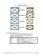
Multi-channel audio uses more than two speakers to represent the sound field.
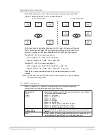
Figure 12. Multi-Channel 5.1 and 7.1 Speaker Positions
5.1 Speaker Positions
RR
Right
Rear
LR
Left
Rear
RF
Right
Front
CTR
Center
LF
Left
Front
Listener
7.1 Speaker Positions
RR
Right
Rear
LR
Left
Rear
RS
Right
Surround
LS
Left
Surround
RF
Right
Front
CTR
Center
LF
Left
Front
Listener
Multi-channel audio, typically embedded in an SDI signal, can be passed through
the FS3 converter unchanged. The multi-channel sound can also be mixed down
to stereo, using the two Mix Down Modules built into the FS3 audio processor.
The default 5.1 to 2 ch. mix-down equation is:
Left Ch Output = LF + (-3dB * CTR) + (-3dB * LR)
Right Ch Output = RF + (-3dB * CTR) + (-3dB * RR)
The default 7.1 to 2 ch. mix-down equation is:
Left Ch Output = LF + (-3dB * CTR) + (-3dB * LS) + (-3dB * LR)
Right Ch Output = RF + (-3dB * CTR) + (-3dB * RS) + (-3dB * RR)
These default settings can be adjusted using the front panel menus or web
interface.
NOTE: The LFE channel is not used in the stereo mix down output, but is passed through
the FS3 audio routing matrix.
13.1 Mix Down Input
When 5.1 Channel or 7.1 Channel is selected above, this parameter selects the
source of the multi-channel audio coming into that mixer.
SDI 1(default)
SDI 2
Fiber 1
Fiber 2
Selects the indicated source. The channel assignments are as follows.
All unused channels are muted:
Input Ch 1 - Left Front
Input Ch 2 - Right Front
Input Ch 3 - Center
Input Ch 4 - Left Rear
Input Ch 5 - Right Rear
Input Ch 6 - LFE (not used in mix down output)
Input Ch 7 - Left Surround (mute in 5.1 mode)
Input Ch 8 - Right Surround (mute in 5.1 mode)
Sig Gen 1KHz
Sig Gen 400Hz
Routes the indicates signal generator to all the active multi-channel
inputs.
Map
This parameters activates a series of related menus to map a specific
input channel to each of the 5 or 7 mixer input channels.