Wellea Monobloc
93
3.
Check the +15V circuit according to corresponding wiring diagram. If CN5 on inverter module output voltage is not +15V means the inverter module is
failed. If voltage output of inverter module is +15V means main PCB is failed.
4.
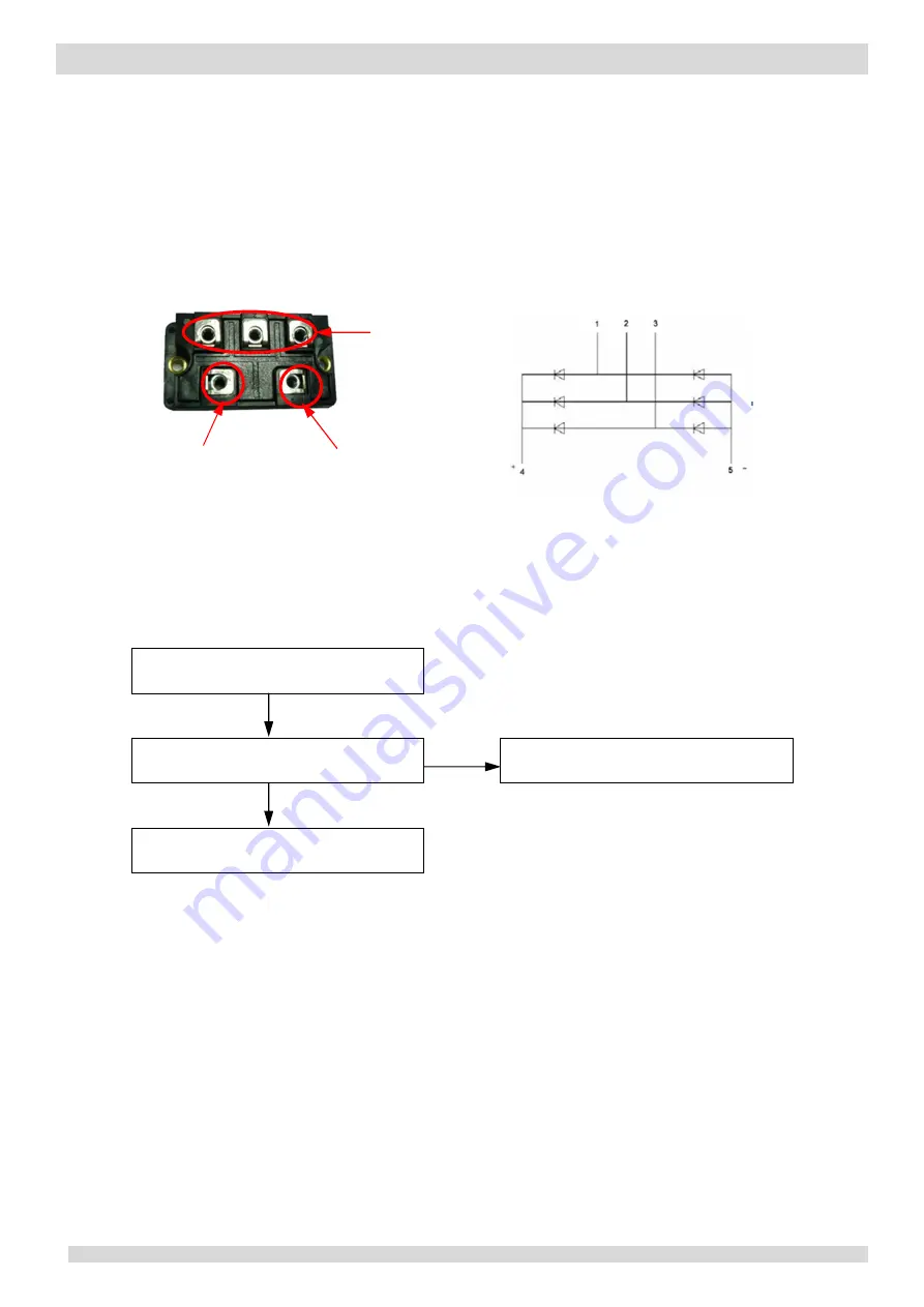
Check the bridge rectifier using one of the following two methods (refer to Figure 4-4.9):
Method 1: measure the resistance between any two of the 5 bridge rectifier terminals. If any of the resistances is close to zero, the bridge rectifier
has failed.
Method 2: dial a multimeter to the diode setting:
- Put the red probe on the DC power output negative terminal (terminal 5) and put the black probe onto each of the AC power input terminals
(terminals 1, 2 and 3) in turn. The voltage between terminal 5 and each of terminals 1, 2 and 3 should be around 0.378V. If the voltage is 0, the
bridge rectifier has failed.
- Put the red probe on the DC power output positive terminal (terminal 4), then put black probe onto each of the AC power input terminals
(terminals 1, 2 and 3) in turn. The voltage between terminal 4 and each of terminals 1, 2 and 3 should be infinite. If the voltage is 0, the bridge
rectifier has failed.
Figure 4-4.9: Bridge rectifier
Situation 2: L1 or L2 error appears after the compressor has been running for a period of time and the compressor
speed is 20 - 30 rps
L1 / L2
Contactor has failed
1
Yes
Replace the contactor
No
Replace the main PCB
Notes:
1.
Check the voltage between the two wires which connect the contactor with the refrigerant system main PCB. If the voltage is 220V AC and the contactor is
open, the contactor has failed.
Single or three phase
AC power input
DC power output:
positive pole
DC power output:
negative pole
Schematic diagram


