


MicroMAX Hardware Installation User Guide
Page 60
Commercial in Confidence
UWB-D00068 Rev J
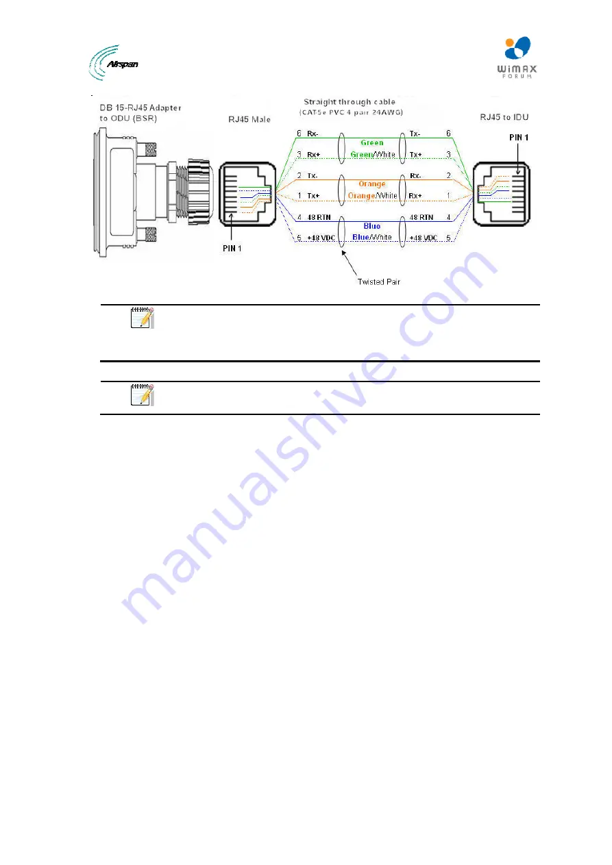
Figure 43 - Pinouts
Note:
The wire color-coding described in the table is Airspan's standard for
wire color-coding. However, if you implement your company's wire color-
coding scheme, ensure that the wires are paired and twisted according to pin
functions listed in the table above (e.g. Rx+ with Rx-).
Note:
The maximum CAT-5e cable length for ODU/IDU connectivity is 100
meters.
To connect the BSR to the SDA-4S:
1. Connect the 15-pin D-type male connector, at one end of the CAT-5e cable, to the BSR's 15-
pin D-type port labeled DATA&PWR&SYNC.
2. Connect the 15-pin D-type male connector, at the other end of the CAT-5e cable, to the
SDA-4S's 15-pin D-type port.
13.2 SDA-4S Type II
The SDA-4S Type II (or the SDA-4SDC) provides one to four RJ-45 (100BaseT) ports for
interfacing with the subscriber's LAN network.
The ports of the SDA-4S model support Auto Negotiation, allowing automatic configuration for the
highest possible speed link (10BaseT or 100BaseT), and Full Duplex or Half Duplex mode. In
other words, the speed of the connected device (e.g. PC) determines the speed at which packets
are transmitted through the specific port. For example, if the device to which the port is connected
is running at 100 Mbps, the port connection will transmit packets at 100 Mbps. Conversely, if the
device to which the port is connected is running at 10 Mbps, the port connection will transmit
packets at 10 Mbps
In addition, the SDA-4S ports support MDI/MDI-X automatic crossover, allowing connection to
straight-through or crossover CAT-5e cables. Therefore, these ports can be connected to either a
hub (i.e. using crossover cables) or a PC (i.e. using straight-through cables).
The cable setup for SDA-4S LAN connectivity is as follows:
¾
Cable:
Straight-through (e.g. when connecting to PC) or crossover (i.e. when connecting
to a hub) CAT-5e Ethernet cable
¾
Connectors:
8-pin RJ-45 at both ends
¾
Connector
pinouts:
•
Straight-through cable (e.g. connecting to a PC)
Содержание MicroMAX
Страница 1: ...UGD D00068 Rev J MicroMAX Hardware Installation User Guide Software Release 7 7 ...
Страница 38: ...MicroMAX Hardware Installation User Guide Page 38 Commercial in Confidence UWB D00068 Rev J ...
Страница 83: ...MicroMAX Hardware Installation User Guide Page 83 Commercial in Confidence UWB D00068 Rev J Figure 75 Level 3 ...


