background image

Chapter 1  Introduction 

AirMux-200

 Installation and Operation Manual 

1-4 Technical 

Specifications


1.3 Technical Specifications 

Air-Interface 

Technology 

OFDM 


Frequency Band 

5.725–5.850 GHz, ISM 


Duplexing Method 

Time Division Duplex (TDD) 


Capacity 

Configurable up to 48 Mbps (See 

Table 1-1


Modulation 

OFDM - BPSK, QPSK, 16QAM, 64QAM 


Channel Resolution 

5 MHz 


Transmitter Power 

18 dBm max 


Antenna Gain 

Integrated: 22 dBi 


Antenna Beamwidth 

4.5

°

 horizontal and vertical 


Range 

Up to 41 km (25.5 miles) 


ODU Installation 

Mast or wall mounting 

LAN Interface 

PHY IF 

10/100BaseT, auto-sensing 


Framing/Coding 

IEEE 802.3/U 


Bridging 

Self-learning, up to 2000 MAC addresses 


Line Impedance 

100


VLAN Support 

Transparent 


Connector 

RJ-45 

E1 Interface 

Data Rate 

Unframed (Transparent) 2.048 MHz 


Connector 

RJ-45 

T1 Interface 

Data Rate 

Unframed (Transparent) 1.544 MHz 


Zero Suppression 

AMI, B8ZS 


Connector 

RJ-45 

Type 

Planar array 

Gain 

28 dBi 

External 
Antenna 
(Optional

)


Antenna Beamwidth 

4.5

°

 horizontal and vertical 


F/B Ratio 

-40 dB max 


Compliance 

ETSI EN 302 085 V1.1.2 (2001-02) 


Polarization 

Linear (vertical or horizontal) 


Input Impedance 

50


Lightning Protection 

DC-grounded 


Connector 

N-type, female 


Range 

Up to 80 km (50 miles), 

Содержание Airmux-200

Страница 1: ...AirMux 200 Installation and Operation Manual Point to Point Wireless TDM IP Multiplexer ...

Страница 2: ......

Страница 3: ...l or any portion of the Manual or the AirMux 200 You are prohibited from and shall not directly or indirectly develop market distribute license or sell any product that supports substantially similar functionality as the AirMux 200 based on or derived in any way from the AirMux 200 Your undertaking in this paragraph shall survive the termination of this Agreement This Agreement is effective upon y...

Страница 4: ...ble to any person for any special or indirect damages including but not limited to lost profits from any cause whatsoever arising from or in any way connected with the manufacture sale handling repair maintenance or use of the AirMux 200 and in no event shall RAD s liability exceed the purchase price of the AirMux 200 DISTRIBUTOR shall be responsible to its customers for any and all warranties whi...

Страница 5: ...ill be attached near the optical transmitter The laser warning symbol may be also attached Please observe the following precautions Before turning on the equipment make sure that the fiber optic cable is intact and is connected to the transmitter Do not attempt to adjust the laser drive current Do not use broken or unterminated fiber optic cables connectors or look straight at the laser beam The u...

Страница 6: ...short circuit current exceeding 35A Always connect the power cord first to the equipment and then to the wall socket If a power switch is provided in the equipment set it to the OFF position If the power cord cannot be readily disconnected in case of emergency make sure that a readily accessible circuit breaker or emergency switch is installed in the building installation Connection of DC Mains Un...

Страница 7: ...lled to provide a separation distance of at least 200 cm from all persons and must not be co located or operating in conjunction with any other antenna or transmitter Outdoor units and antennas should be installed ONLY by experienced installation professionals who are familiar with local building and safety codes and wherever applicable are licensed by the appropriate government regulatory authori...

Страница 8: ...hone and data lines FXO Foreign Exchange Office xDSL with feeding voltage U Interface ISDN TNV 3 Telecommunication Network Voltage 3 Ports whose normal operating voltage exceeds the limits of SELV usually up to 120 VDC or telephone ringing voltages on which overvoltages from telecommunication networks are possible The signals between the IDU and ODU are TNV 1 Always connect a given port to a port ...

Страница 9: ...uration The compliance of the equipment with the regulations for conducted emission on the data lines is dependent on the cable quality The emission is tested for UTP with 80 dB longitudinal conversion loss LCL Unless otherwise specified or described in the manual TNV 1 and TNV 3 ports provide secondary protection against surges on the data lines Primary protectors should be provided in the buildi...

Страница 10: ...uct is expressly forbidden in accordance to FCC rules CFR47 part 15 204 Canadian Emission Requirements for the IDU This Class B digital apparatus meets all the requirements of the Canadian Interference Causing Equipment Regulation Cet appareil numérique de la classe B respecte toutes les exigences du Règlement sur le matériel brouilleur du Canada Statement according to Directive 1999 5 EC Hereby R...

Страница 11: ...ormance of the link operating at the system requirements The Link Budget Calculator Utility can be found on the Technical Documentation CD ROM 3 Install the AirMux 200 software on the laptop the installation takes a few minutes The software installation leaves the AirMux Manager icon on the desktop Performing Installation To install the ODU 1 At site A route the ODU cable from the ODU location on ...

Страница 12: ...mast or brackets using cable ties 7 Repeat the procedure at site B To align the ODU 1 Connect power to the site A IDU After approximately 20 seconds the ODU beeper starts beeping this is normal 2 Verify normal operation of the IDU by the LED indications on the front panel Indicator Color Status PWR Green ON IDU Orange Green Blinks for 40 seconds during startup Blinking slowly shows normal operatio...

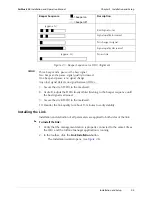
Страница 13: ...equence beeper on beeper off Description approx 1s Best Signal so far Signal quality increased No change in signal Signal quality decreased approx 2s No air link Three beeps and a pause is the best signal Two beeps and a pause signal quality increased One beep and pause is no signal change Any other signal detects no signal between ODUs 8 Secure the site B ODU to the mast wall 9 At site A adjust t...

Страница 14: ...he yellow range for Ethernet service Achieve the best possible link quality values In case of radio link loss verify the ODU alignment or change the radio channel in both sides of the link When the radio link resumes continue the installation process Connecting User Equipment To connect user equipment to the IDU 1 Connect the user equipment such as PBX to the IDU rear panel RJ 45 port designated T...

Страница 15: ... AirMux Manager Software 2 7 Aligning the AirMux 200 ODUs 2 8 Installing the Link 2 9 Connecting the User Equipment 2 15 Chapter 3 Configuration 3 1 Performing Configuration of AirMux 200 3 1 Configuring Service Parameters 3 5 Editing the Configuration Parameters 3 8 Defining the Management Addresses 3 9 Chapter 4 Operation 4 1 Indicators 4 1 Front Panel Indicators 4 1 Rear Panel Indicators 4 2 4 ...

Страница 16: ...7 2 4 Main Menu 2 8 2 5 Beeper Sequence for ODU Alignment 2 9 2 6 Link Installation Wizard 2 10 2 7 Installation Wizard System dialog box 2 11 2 8 Installation Wizard Channel Select dialog box 2 12 2 9 Installation Wizard Rates dialog box 2 13 2 10 Installation Wizard Services dialog box 2 14 2 11 Installation Wizard Finish Screen 2 15 3 1 AirMux Manager Main Menu 3 1 3 2 Configuration Link Wizard...

Страница 17: ...4 5 4 Remote Internal Loopback 5 5 5 5 Remote External Loopback 5 5 5 6 Local Internal Loopback 5 6 List of Tables 1 1 AirMux 200 Throughput 1 2 4 1 IDU Front Panel LEDs 4 1 4 2 WAN LAN LEDs 4 2 4 3 TDM Traffic Indicators 4 2 4 4 AirMux 200 Indicators at Startup 4 3 5 1 AirMux 200 Alarms and Information Messages 5 1 5 2 Troubleshooting with AirMux 200 LEDs 5 6 ...

Страница 18: ...Table of Contents iv AirMux 200 Installation and Operation Manual ...

Страница 19: ...Up to 41 km 25 5 miles AirMux 200 PBX PBX E1 T1 E1 T1 E1 T1 E1 T1 Figure 1 1 Typical Application Features Wireless Link AirMux 200 delivers up to 48 Mbps data rate for Ethernet and E1 T1 traffic The system supports ISM frequency bands and can be configured to operate over several frequency channels with a carrier step resolution of 5 MHz AirMux 200 operation complies with the FCC 47CFR Part 15 and...

Страница 20: ...parent VLAN support Traffic handling is provided by a MAC level self learning bridge TDM Interface The AirMux 200 TDM interface accepts E1 or T1 traffic supporting the following Unframed operation E1 and T1 AMI and B8ZS zero suppression T1 Management AirMux 200 has full local and remote management capabilities The user friendly SNMP based management tool provides full end to end configuration even...

Страница 21: ...AirMux 200 Unit with Integrated Antenna The front panel of the indoor unit IDU includes five LEDs which display the status of E1 T1 wireless link self test results ODU to IDU link and power status For a detailed description of the front panel LEDs see Chapter 4 The rear panel of the indoor unit IDU includes the power WAN LAN and E1 T1 and ODU connectors The rear panel LEDs are described in Chapter...

Страница 22: ...allation Mast or wall mounting LAN Interface PHY IF 10 100BaseT auto sensing Framing Coding IEEE 802 3 U Bridging Self learning up to 2000 MAC addresses Line Impedance 100Ω VLAN Support Transparent Connector RJ 45 E1 Interface Data Rate Unframed Transparent 2 048 MHz Connector RJ 45 T1 Interface Data Rate Unframed Transparent 1 544 MHz Zero Suppression AMI B8ZS Connector RJ 45 Type Planar array Ga...

Страница 23: ...nsumption 20W max ODU and IDU Connector 2 pin Physical Outdoor Unit ODU with integrated antenna Height 305 mm 12 in Width 305 mm 12 in Depth 58 mm 2 3 in Weight 3 3 kg 7 2 lb Indoor Unit IDU E Height 44 mm 1 7 in 1U Width 237 mm 9 3 in Depth 170 mm 6 7 in Weight 0 58 kg 1 4 lb External Antenna Optional Height 600 mm 23 6 in Width 600 mm 23 6 in Depth 51 mm 2 in Weight 5 kg 11 lb Environment Outdoo...

Страница 24: ...Chapter 1 Introduction AirMux 200 Installation and Operation Manual 1 6 Technical Specifications ...

Страница 25: ...rMux 200 System AirMux 200 system comprises the following units Outdoor Unit ODU An enclosed aluminum frame with a front sealed plastic cover containing an integrated transceiver with an antenna RF module modem and standard interfaces The ODU stores all the configuration parameters of the AirMux 200 system ODU includes a power connector which receives 48 VDC and RJ 45 for Ethernet traffic from the...

Страница 26: ... condensing Before starting the installation refer to the Link Budget Calculator utility found on the Last Mile CD Rom in order to calculate the expected performance of the link operating at your system requirements 2 3 Package Contents The AirMux 200 packages include the following items ODU Package Containing ODU Mast Wall mounting kit plus mounting instructions AIRMUX 200 Manager installation CD...

Страница 27: ... 2 spanner ODU to IDU cable if not ordered Outdoor class CAT 5e 4 twisted pairs Cable ties 2 5 Installation and Setup The AirMux 200 system installation is achieved by following the steps listed below 1 Installing ODU at both sites of the link 2 Assembling the ODU cable and connecting ODU to IDU at both sites 3 Connecting the power 4 Aligning the ODUs 5 Installing the management program on the net...

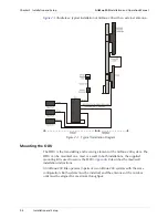
Страница 28: ...he ODU is the transmitting and receiving element of the AirMux 200 system The ODU can be mounted on a mast or a wall In both installations the supplied mounting kit is used to secure the ODU Appendix B describes the mast wall installation instructions An AirMux 200 link operates in pairs of two AirMux 200 systems with the same configuration Both systems must be installed and the antennas of the ou...

Страница 29: ...cedure at the remote site Do not tightly secure the ODU to its mounting brackets until the alignment process of the antenna is complete When installing the ODU it is important to check that there are no direct obstructions in front of the ODU or interference from man made obstacles Connecting the ODU to the IDU The ODU cable conducts all the user traffic between the IDU and the ODU The ODU cable a...

Страница 30: ...Mux 200 management application can be used to configure AirMux 200 units Connecting the Power Before connecting any cable the protective earth terminals of the AC DC adapter must be connected to the protective ground conductor of the mains power cord If you are using an extension cord power cable make sure it is grounded as well Any interruption of the protective grounding conductor inside or outs...

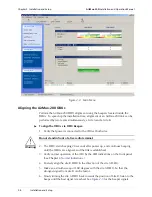
Страница 31: ...esktop or from the Start menu point to Programs point to AirMux Manager and then click AirMux Manager The password IP request dialog appears Figure 2 3 Login Screen 3 Select the suitable option Select Local Connection Broadcast Enter IP address of the ODU The IP address is defined later during link configuration 4 Enter the password Default password admin see Chapter 4 for Changing the Password Th...

Страница 32: ...at both sites Do not stand in front of a live radio terminal 2 The ODU starts beeping 20 seconds after power up and continues beeping until the ODUs are aligned and the link is established 3 Verify normal operation of the IDU by the LED indications on the front panel See Chapter 4 Normal Indications 4 Coarsely align the site B ODU in the direction of the site A ODU 5 Make an azimuth sweep of 180 d...

Страница 33: ...er signal detects no signal between ODUs 7 Secure the site A ODU to the mast wall 8 At site B adjust the ODU slowly whilst listening to the beeper sequence until the best signal is attained 9 Secure the site B ODU to the mast wall 10 Monitor the link quality for about 15 minutes to verify stability Installing the Link Installation and definition of all parameters are applied to both sides of the l...

Страница 34: ...ion and Setup AirMux 200 Installation and Operation Manual 2 10 Installation and Setup Figure 2 6 Link Installation Wizard 3 Click next to proceed with the Installation procedure The system dialog box opens see Figure 2 7 ...

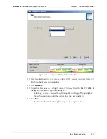
Страница 35: ...a SSID System ID The SSID must include at least eight alphanumeric characters Up to 24 characters are allowed Both sites of a link must always have the same number The ID is initially factory set 5 Enter Link name for the link identification 6 Enter a name for site 1 7 Enter a name for site 2 8 Click Next The Channel Select dialog box appears see Figure 2 8 Notes ...

Страница 36: ...lect the required operating channel The pull down list shows the ISM frequencies available The Manual option allows you a User defined channel within the system frequency band Selecting a new channel causes the system quality to change The quality bar shows the adjustment until the system finds the best quality link 10 Click Next The Rate Select dialog box appears see Figure 2 9 ...

Страница 37: ...ices required Table 1 1 lists throughput rates and capacities 12 Click Evaluate 13 A question box pops up asking if you want to re evaluate the link Click Yes to change the rate No to keep the existing rate Selecting a new rate causes the system quality to change The quality bar shows the adjustment until the system finds the best quality link 14 Click Next The Service Parameters dialog box appear...

Страница 38: ... E1 T1 field if you intend to transmit E1 T1 data and Ethernet data The Ethernet BW field shows the remaining bandwidth in Mbps available for Ethernet The available bandwidth depends on the number of E1 T1 ports selected Select the Ethernet field if you intend to transmit Ethernet data only 16 Click Next The Finish screen appears see Figure 2 11 The Finish screen shows a summary of the link config...

Страница 39: ...nal strength RSS in the Main menu is according to expected results 19 Connecting the User Equipment The IDU is a standalone desktop wall mounted or rack installed unit Figure 2 2 illustrates a typical rear panel of the IDU To connect user equipment to the IDU 1 Connect user E1 T1 traffic to the IDU rear panel RJ 45 port designated Trunk Refer to Appendix A for the connector pinout 2 Connect user h...

Страница 40: ...Chapter 2 Installation and Setup AirMux 200 Installation and Operation Manual 2 16 Installation and Setup ...

Отзывы: