


AirMux-200
Installation and Operation Manual
Chapter 1 Introduction
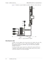
Physical Description
1-3
1.2 Physical Description
AirMux-200 system consists of an Outdoor Unit (ODU) and an Indoor Unit (IDU).
Figure 1-2
illustrates an AirMux-200 unit assembly.
Figure 1-2. AirMux-200 Unit with Integrated Antenna
The front panel of the indoor unit (IDU) includes five LEDs, which display the
status of E1/T1, wireless link, self-test results, ODU-to-IDU link, and power status.
For a detailed description of the front panel LEDs, see
Chapter 4
.
The rear panel of the indoor unit (IDU) includes the power, WAN, LAN and E1/T1,
and ODU connectors. The rear panel LEDs are described in
Chapter 4
, and the
wiring specifications detailed in
Appendix A
.
Содержание Airmux-200
Страница 1: ...AirMux 200 Installation and Operation Manual Point to Point Wireless TDM IP Multiplexer ...
Страница 2: ......
Страница 18: ...Table of Contents iv AirMux 200 Installation and Operation Manual ...
Страница 24: ...Chapter 1 Introduction AirMux 200 Installation and Operation Manual 1 6 Technical Specifications ...
Страница 40: ...Chapter 2 Installation and Setup AirMux 200 Installation and Operation Manual 2 16 Installation and Setup ...


