background image

19. Configuration Example: Policy 


AirLive RS-2500 User’s Manual 

156

19 

19. 

Configuration Example: 

Policy Setting


19.1 Configuration Example (1) - Traffic Log, Statistic 

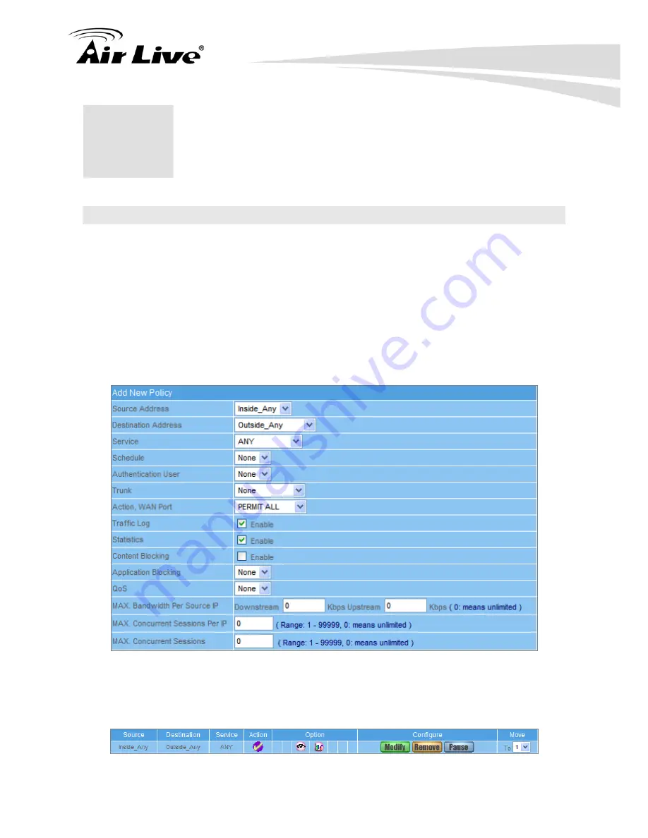
Set up the policy that can monitor the internal users. (Take Traffic Log and Statistics for 

example) 


STEP 1

Enter the following setting in 

Outgoing


Policy

 Click 

New Entry


 Select 

Traffic Log


 Select 

Statistics


 Click 

OK

 (Figure 19-1) 


Figure 19-1 Setting the different Policies 


STEP 2

Complete the setting of Logging, Statistics, and Alarm Threshold in 

Outgoing 

Policy

: (Figure 19-2) 


Figure 19-2 Complete Policy Setting 


Содержание RS-2500

Страница 1: ...User s Manual Dual WAN Security VPN Gateway RS 2500 ...

Страница 2: ...l photocopying or recording without the written consent of OvisLink Corp OvisLink Corp has made the best effort to ensure the accuracy of the information in this user s guide However we are not liable for the inaccuracies or errors in this guide Please use with caution All information is subject to change without notice All Trademarks are properties of their respective holders ...

Страница 3: ...7 2 4 Hardware Installation 7 2 5 LED Table 8 2 6 Restore Settings to Default 8 3 Configuring the RS 2500 9 3 1 Important Information 9 3 2 Prepare your PC 9 3 3 Management Interface 10 3 4 Introduction to Web Management 11 3 4 1 Getting into Web Management 11 3 5 Initial Configurations 14 4 Web Management 18 4 1 About RS 2500 s Menu Structure 18 4 2 Remote Web Management 19 5 Administration 20 5 ...

Страница 4: ...Table 37 6 8 Language 37 7 Interface 38 7 1 LAN 40 7 2 WAN 41 7 3 DMZ 46 8 Address 47 8 1 LAN 48 8 2 LAN Group 50 9 Service 53 9 1 Pre defined 54 9 2 Custom 55 9 3 Group 58 10 Schedule 60 11 QoS 62 12 Authentication 68 12 1 Auth Setting 68 12 2 Auth User 71 13 Content Blocking 75 13 1 URL 75 13 2 Script 77 13 3 Download 79 13 4 Upload 81 14 Application Blocking 83 ...

Страница 5: ...ice to Office 134 17 5 PPTP VPN Office to Client 143 18 Policy 152 19 Configuration Example Policy Setting 156 19 1 Configuration Example 1 Traffic Log Statistic 156 19 2 Configuration Example 2 Specific WAN Addresses Content Blocking Application Blocking 159 19 3 Configuration Example 3 Authentication Schedule 164 19 4 Configuration Example 4 Virtual Server 167 19 5 Configuration Example 5 QoS Vi...

Страница 6: ...counting Report 202 22 3 Statistic 211 22 4 Diagnostic 216 22 5 Wake On Lan 220 22 6 Status 221 23 Frequent Asked Questions 225 24 Specifications 229 24 1 Hardware Features 229 25 Network Glossary 234 25 1 Interface 234 25 2 System 235 25 3 VPN 238 25 4 Anomaly Flow IP 240 ...

Страница 7: ...standing Security VPN Gateway than before 1 2 How to Use This Guide RS 2500 is an advanced VPN Security Gateway with many functions It is recommended that you read through the entire user s guide whenever possible The user guide is divided into different chapters You should read at least go through the first 3 chapters before attempting to install the device Chapter 1 Introduction This chapter is ...

Страница 8: ...s for the specific device in LAN WAN or DMZ so the Policy setting can be modified to restrict the service precisely Chapter 9 Service In this chapter it lists the standard protocol for user s reference and it also allows user creating non standard port number for the request In the end the Address setting will be assigned to Mapped IP Virtual Server or enabled by Policy setting Chapter 10 Schedule...

Страница 9: ...ation Example Policy Setting We list several Policy setting for your reference and you can know better how to configure it Chapter 20 Web VPN SSL VPN This chapter will explain you the Web VPN SSL VPN function and we also list the example for your reference about how to configure it Chapter 21 Anomaly Flow IP This chapter is an introduction to tell user how to configure RS 2500 for the protection f...

Страница 10: ...ware that either increase software functions or provide bug fixes for RS 2500 You can reach our on line support center at the following link http www airlive com support support_2 jsp Since 2009 AirLive has added the Newsletter Instant Support System on our website AirLive Newsletter subscribers receives instant email notifications when there are new download or tech support FAQ updates for their ...

Страница 11: ... IM P2P Blocking Content Blocking User Authentication QoS Max Bandwidth Per Source IP Max Concurrent Sessions Per Source IP Dual WAN Load Balance and Fail over Multiple Subnet Custom Service Definition for IP TCP UDP Detect and block the anomaly flow IP Policy based Firewall DMZ Transparent Schedule Static Route RIPv2 Web Management ...

Страница 12: ...can use CAT 5 Ethernet cable according to the length you need The RS 2500 must be installed with 5V adapter Please do not use the other voltage of adapter During upgrading firmware please do not renew or close the webpage otherwise it could crash the firmware Please do not use FTP to transfer firmware file because the firmware could be transferred incompletely If user upgrades RS 2500 with incompl...

Страница 13: ...product 2 4 Hardware Installation 1 Plug in power adapter to RS 2500 and electric outlet at wall 2 Connect an Ethernet cable to PC and RS 2500 LAN port 3 Wait for RS 2500 Status LED to stop blinking the light 4 PC should get the IP address from RS 2500 DHCP server and now you can login to RS 2500 and configure the setting ...

Страница 14: ...s Steady Green Ready to use Blinking At the booting process WAN1 2 LAN DMZ Steady Green Cable is connected Blinking Packets is sending receiving 2 6 Restore Settings to Default If you have forgotten your RS 2500 s IP address or password you can restore your RS 2500 to the default settings by pressing on the reset button for more than 10 seconds You can find the reset button at back panel Please se...

Страница 15: ...ase wait for 2 minutes for RS 2500 to finish boot up 3 2 Prepare your PC The default IP address of this product is 192 168 1 1 and the default subnet mask is 255 255 255 0 These addresses can be changed on your need but the default values are used in this manual If the TCP IP environment of your computer has not yet been configured you can refer to the example 1 Configure IP as 192 168 1 2 subnet ...

Страница 16: ...rk card on your computer must be lighted 2 Is the TCP IP environment of your computers properly configured Tip If the IP address of this product is 192 168 1 1 the IP address of your computer must be 192 168 1 X and default gateway must be 192 168 1 1 3 3 Management Interface The RS 2500 can be configured using one the management interfaces below Web Management HTTP You can manage your RS 2500 by ...

Страница 17: ...is HTTPS are encrypted for extra security Therefore we will discuss them together as Web Management on this guide If you are placing the RS 2500 behind router or firewall you might need to open virtual server ports to RS 2500 on your firewall router HTTP TCP Port 80 HTTPS TCP UDP Port 443 3 4 1 Getting into Web Management Normal Web Management HTTP To get into the Normal Web Management simply type...

Страница 18: ...address field The 192 168 1 1 is RS 2500 s default IP address If the IP address is changed the address entered in the browser should change also A security warning screen from your browser will then pop up depending on the browser you use Please follow step below to clear the security screen Internet Explorer Select Yes to proceed Firefox 1 Select or you can add an exception 1 ...

Страница 19: ...Configuring the RS 2500 13 AirLive RS 2500 User s Manual 2 Click on Add Exception 2 3 Click on Get Certificate Then please enter RS 2500 s IP address Finally please click on Confirm Security Exception 3 4 ...

Страница 20: ...rity VPN Gateway as 192 168 1 1 in the address bar 3 A pop up screen will appear and prompt for a username and password Enter the default login username admin and password airlive of Administrator STEP 2 After entering the username and password the Security VPN Gateway WEB UI screen will display Select the Interface tab on the left menu and a sub function list will be displayed Click on WAN from t...

Страница 21: ...menu and then click on Outgoing from the sub function list STEP 4 Click on New Entry button STEP 5 When the New Entry option appears enter the following configuration Source Address select Inside_Any Destination Address select Outside_Any Service select ANY Action select Permit ALL Click on OK to apply the changes ...

Страница 22: ...en the screen below is displayed Make sure that all the computers that are connected to the LAN port have their Default Gateway IP Address set to the Security VPN Gateway s LAN IP Address i e 192 168 1 1 At this point all the computers on the LAN network should gain access to the Internet immediately ...

Страница 23: ...y IP Flow and Monitor Each subject includes several sub object settings and each sub object also includes several functions for user s configuration RS 2500 was designed as the policy based firewall it means user should configure Policy Object setting and enable the function at Policy Main Subject Sub Object Functions System It includes Administration Configure and Logout sub objects The System su...

Страница 24: ...cy Object settings Please refer to chapter 18 Web VPN SSL VPN RS 2500 provides Web VPN SSL VPN function to allow remote user connecting and accessing to router s LAN resource Please refer to chapter 20 Anomaly IP Flow It works to define the rule to block hacker from Internet or Intranet Please refer to chapter 21 Monitor It includes Log Accounting Report Statistic Diagnostic Wake on Lan and Status...

Страница 25: ...S 2500 The admin user name cannot be removed and the sub admin user can be removed or modified The default Account admin Password airlive 5 5 Administration Privilege The privileges of Administrators Admin or Sub Admin The username of the main Administrator is Administrator with reading writing privilege Administrator also can change the system setting log system status and to increase or delete s...

Страница 26: ...5 Confirm Password 12345 STEP 3 Click OK to add the user or click Cancel to cancel it Figure 5 1 Add New Sub Admin Modify the Administrator s Password STEP 1 In the Admin WebUI locate the Administrator name you want to edit and click on Modify in the Configure field STEP 2 The Modify Administrator Password WebUI will appear Enter the following information Password admin New Password 52364 Confirm ...

Страница 27: ...ng HTTP and HTTPS Click OK Complete add new permitted IPs Figure 5 4 Figure 5 3 Setting Permitted IPs WebUI Figure 5 4 Complete Add New Permitted IPs To make Permitted IPs be effective it is suggested to cancel the Ping HTTP and HTTPS selection in LAN WAN or DMZ Interface setting Before canceling the WebUI selection of Interface user must set up the Permitted IPs first otherwise it would cause the...

Страница 28: ...ck OK and the system will update automatically Figure 5 5 Figure 5 5 Software Update It takes 4 minutes to update software The system will reboot after update During the updating time please don t turn off the PC or close WebUI It may cause some unexpected mistakes Strong suggests updating the software from LAN to avoid unexpected mistakes 5 4 Logout STEP 1 Click Logout in System to protect the sy...

Страница 29: ...ble and Language settings 6 1 Setting System Settings Exporting STEP 1 In System Setting WebUI click on button next to Export System Setting to Client STEP 2 When the File Download pop up window appears choose the destination place where to save the exported file and click on Save The setting value of RS 2500 will copy to the appointed site instantly Figure 6 1 Figure 6 1 Select the Destination Pl...

Страница 30: ...o Import System Setting from Client When the Choose File pop up window appears select the file to which contains the saved RS 2500 Settings then click OK Figure 6 2 STEP 2 Click OK to import the file into the RS 2500 Figure 6 3 Figure 6 2 Enter the File Name and Destination of the Imported File Figure 6 3 Upload the Setting File WebUI ...

Страница 31: ...r when the network is being attacked by hackers or when emergency conditions occur It can be set from Anomaly Flow IP Setting to detect Hacker Attacks Enabling E mail Alert Notification STEP 1 Select Enable E mail Alert Notification under E Mail Settings STEP 2 Sender Address Required by some ISPs Enter the Sender Address STEP 3 SMTP Server IP Enter SMTP server s IP address STEP 4 E Mail Address 1...

Страница 32: ...ator wants to enter WebUI from WAN will have to change the port number of browser For example http 61 62 108 172 8080 MTU Setting It provides the Administrator to modify the networking package length anytime Its default value is 1500 Bytes Link Speed Duplex Mode Setting By this function can set the transmission speed and mode of WAN Port when connecting other device Dynamic Routing RIPv2 Select to...

Страница 33: ...ket Logging After enable this function the RS 2500 will record packet which source or destination IP address is RS 2500 and record in Traffic Log for System Manager to inquire about System Reboot Once this function is enabled the RS 2500 will be rebooted STEP 1 Reboot RS 2500 Click Reboot button next to Reboot RS 2500 Appliance STEP 2 A confirmation pop up page will appear STEP 3 Follow the confir...

Страница 34: ...er Figure 6 7 STEP 2 Click the down arrow to select the offset time from GMT STEP 3 If necessary select Enable daylight saving time setting STEP 4 Enter the Server IP Name with which you want to synchronize STEP 5 Set the interval time to synchronize with outside servers Figure 6 7 System Time Setting Click on the Sync button and then the RS 2500 s date and time will be synchronized to the Adminis...

Страница 35: ...face Netmask The Multiple Subnet IP address range setting Configuration Example RS 2500 WAN1 10 10 10 1 connect to the ISP Router 10 10 10 2 and the subnet that provided by ISP is 162 172 50 0 24 To connect to Internet WAN2 IP 211 22 22 22 connects with ATUR Adding Multiple Subnet Add the following settings in Multiple Subnet of System function Click on New Entry Alias IP of LAN Interface Enter 16...

Страница 36: ...net and 162 172 50 0 24 So if LAN IP is 192 168 1 xx it must use NAT Mode to access to the Internet In Policy it only can setup to access to Internet by WAN2 If by WAN1 Routing mode then it cannot access to Internet by its virtual IP 162 172 50 xx it uses Routing mode through WAN1 The Internet Server can see your IP 162 172 50 xx directly And uses NAT mode through WAN2 The Internet Server can see ...

Страница 37: ...urement department subnet 192 168 4 1 24 LAN 168 85 88 250 WAN 5 Accounting department subnet 192 168 5 1 24 LAN 168 85 88 249 WAN The first department R D department had set while setting interface IP the other four ones have to be added in Multiple Subnet After completing the settings each department uses the different WAN IP Address to connect to the Internet The settings of each department are...

Страница 38: ... with different IP subnet can access Internet at the same time Figure 6 10 11 Figure 6 10 Route Table UI Figure 6 11 Route Table UI Destination IP Netmask The target IP subnet of routing rule Gateway Indicate the IP address of router that will route packets to target subnet Interface Indicate the interface to send out the routing packets ...

Страница 39: ...ver 1 Enter the distributed IP address of WINS Server1 WINS Server 2 Enter the distributed IP address of WINS Server2 LAN Interface Client IP Address Range 1 Enter the starting and the ending IP address dynamically assigning to DHCP clients The default value is 192 168 1 2 to 192 168 1 254 it must be in the same subnet Client IP Address Range 2 Enter the starting and the ending IP address dynamica...

Страница 40: ... WebUI When selecting Automatically Get DNS the DNS Server will be locked as LAN Interface IP Using Occasion When the system Administrator starts Authentication the users first DNS Server must be the same as LAN Interface IP in order to enter Authentication WebUI ...

Страница 41: ...ord Enter the password Domain name Enter Your host domain name Click OK to add Dynamic DNS Figure 6 14 Figure 6 13 DDNS WebUI Figure 6 14 Complete DDNS Setting Chart Meaning Update successfully Incorrect username or password Connecting to server Unknown error If System Administrator had not registered a DDNS account click on Sign up then can enter the website of the provider If you do not select A...

Страница 42: ...gs function and click on New Entry Host Name The domain name of the server Virtual IP Address The virtual IP address is corresponding to the Host Click OK to add Host Table Figure 6 15 Figure 6 15 Add New Host Table To use Host Table the user PC s first DNS Server must be the same as the LAN Port or DMZ Port IP of RS 2500 That is the default gateway 6 8 Language Select the Language version English...

Страница 43: ... ICMP User can define the IP address and RS 2500 will ping the address to verify WAN port s connection status DNS Another way to verify the connection status by checking the DNS server and Domain Name configured by user Upstream Downstream Bandwidth The System Administrator can set up the correct Bandwidth of WAN network Interface here Auto Disconnect The PPPoE connection will automatically discon...

Страница 44: ...ction is built up all the packets from the same source IP will pass through the same WAN interface By Destination IP The RS 2500 will allocate the WAN connection corresponding to the destination IP once the connection is built up all the packets to the same destination IP will pass through the same WAN interface The connection will be re assigned with WAN interface when the connections are stopped...

Страница 45: ...K Figure 7 1 Figure 7 1 Setting LAN Interface WebUI The default LAN IP Address is 192 168 1 1 After the Administrator setting the new LAN IP Address on the computer he she have to restart the System to make the new IP address effective when the computer obtain IP by DHCP Do not cancel WebUI selection before not setting Permitted IPs yet because the Administrator cannot be allowed to enter the RS 2...

Страница 46: ...ndicator Site IP can select from Assist Figure 7 3 DNS Enter two different DNS Server IP Address and Domain Name can select from Assist Figure 7 4 Setting time of seconds between sending alive packet Figure 7 3 ICMP Connection Figure 7 4 DNS Service Connection test is used for RS 2500 to detect if the WAN can connect or not So the Alive Indicator Site IP DNS Server IP Address or Domain Name must b...

Страница 47: ... provided by ISP If you select Fixed please enter IP Address Netmask and Default Gateway 5 Enter Max Downstream Bandwidth and Max Upstream Bandwidth According to the flow that user applies 6 Enter the value on the setting of Auto Disconnect if idle for minutes Range 1 99999 0 means always connected the default value is 0 Always connected 7 Select Ping HTTP and HTTPS and click OK Figure 7 6 Figure ...

Страница 48: ...ress is required for ISP then click on Clone MAC Address to obtain MAC IP automatically 4 Hostname Enter the hostname provided by ISP 5 Domain Name Enter the domain name provided by ISP 6 User Name and Password are the IP distribution method according to Authentication way of DHCP protocol 7 Enter Max Downstream Bandwidth and Max Upstream Bandwidth According to the flow applied by user 8 Select Pi...

Страница 49: ...2 Enter IP Address Netmask and Default Gateway that provided by ISP 3 Enter DNS Server1 and DNS Server2 4 Enter Max Downstream Bandwidth and Max Upstream Bandwidth According to the flow applied by user 5 Select Ping HTTP and HTTPS and click OK Figure 7 10 Figure 7 9 Static IP Address Connection Figure 7 10 Complete Static IP Address Connection Setting ...

Страница 50: ...e to ping the RS 2500 and enter the WebUI WAN network It may influence network security The suggestion is to Cancel Ping HTTP and HTTPS after all the settings have finished And if the System Administrator needs to enter UI from WAN he she can use Permitted IPs to enter The setting of WAN2 Interface is almost the same as WAN1 except that WAN2 has a selection of Disable The System Administrator can ...

Страница 51: ...lick OK Figure 7 12 Figure 7 12 Setting DMZ Interface Address NAT Mode WebUI Setting DMZ Interface Address Transparent Mode STEP 1 Select DMZ Interface STEP 2 Select Transparent Mode in DMZ Interface Select DMZ_Transparent in DMZ Interface STEP 3 Select Ping HTTP and HTTPS STEP 4 Click OK Figure 7 13 Figure 7 13 Setting DMZ Interface Address Transparent Mode WebUI The Transparent Mode of DMZ setti...

Страница 52: ... addresses and names of address groups shown in the address table the Administrator can use these names as the source address or destination address of control policies The address table should be setup before creating control policies so that the Administrator can pick the names of correct IP addresses from the address table when setting up control policies 8 8 Address Name The System Administrat...

Страница 53: ...ign the specific IP to static users and restrict them to access FTP net service only through policy STEP 1 Select LAN in Address and enter the following settings Click New Entry button Figure 8 1 Name Enter Jacky IP Address Enter 192 168 1 2 Netmask Enter 255 255 255 255 MAC Address Enter the user s MAC Address 00 4F F3 F5 D3 54 Select Get static IP address from DHCP Server Click OK Figure 8 2 Fig...

Страница 54: ...pecific IP to static users in Outgoing Policy and restrict them to access FTP net service only through policy Figure 8 4 Figure 8 4 Complete the Policy of Restricting the Specific IP to Access to Internet When the System Administrator creates the Address list he she can choose the way of clicking on to make the RS 2500 to fill out the user s MAC Address automatically The setting mode of WAN and DM...

Страница 55: ...ting to represent the whole subnet 8 2 LAN Group Setup a Policy that only allows partial users to connect with specific IP External Specific IP STEP 1 Setting several LAN network Address Figure 8 5 Figure 8 5 Setting Several LAN Network Address STEP 2 Enter the following settings in LAN Group of Address Click New Entry Figure 8 6 Enter the Name of the group Select the users in the Available Addres...

Страница 56: ...te Adding LAN Address Group The setting mode of WAN Group and DMZ Group of Address are the same as LAN Group STEP 3 Enter the following settings in WAN of Address function Click New Entry Figure 8 8 Enter the following data Name IP Address Netmask Click OK Figure 8 9 Figure 8 8 Add New WAN Address ...

Страница 57: ...ess STEP 4 In Outgoing Policy select LAN Group as Source Address and select WAN Address as the Destination Address Figure 8 10 8 11 Figure 8 10 To Exercise Address Setting in Policy Figure 8 11 Complete the Policy Setting The Address function really takes effect only if uses with Policy ...

Страница 58: ...hree sub menus under Service which are Pre defined Custom and Group The Administrator can simply follow the instructions below to define the protocols and port numbers for network communication applications Users then can connect to servers and other computers through these available network services How to use Service The Administrator can add new service group names in the Group option under Ser...

Страница 59: ...TCP Service For example AFPoverTCP AOL BGP FTP FINGER HTTP HTTPS IMAP SMTP POP3 GOPHER InterLocator IRC L2TP LDAP NetMeeting NNTP PPTP Real Media RLOGIN SSH TCP ANY TELNET VDO Live WAIS WINFRAME X WINDOWS MSN etc UDP Service For example IKE DNS NFS NTP PC Anywhere RIP SNMP SYSLOG TALK TFTP ICMP Service Foe example PING TRACEROUTE etc ...

Страница 60: ...network card of clients The range is 0 65535 suggest to use the default range Server Port The port number of custom service Configuration Example Allow external user to communicate with internal user by VoIP through policy VoIP Port TCP 1720 TCP 15328 15333 UDP 15328 15333 STEP 1 Set LAN and LAN Group in Address function as follows Figure 9 1 9 2 Figure 9 1 Setting LAN Address Book WebUI Figure 9 ...

Страница 61: ...ort and set the Server Port as 15328 15333 Click OK Figure 9 4 Figure 9 3 Add User Define Service Figure 9 4 Complete the Setting of User Define Service of VoIP Under general circumstances the range of port number of client is 0 65535 Change the client range in Custom of is not suggested If the port numbers that enter in the two spaces are different port number then enable the port number under th...

Страница 62: ...olicy Figure 9 6 Figure 9 6 Configure Incoming Policy and allow External VoIP connecting with Internal VoIP STEP 5 In Outgoing Policy complete the setting of internal users using VoIP to connect with external network VoIP Figure 9 7 Figure 9 7 Complete the Policy for Internal VoIP to connect with External VoIP Service must cooperate with Policy and Virtual Server that the function can take effect ...

Страница 63: ...licy rules you create the less performance you get Configuration Example Restrict the specific users can only access specific service resources HTTP POP3 SMTP DNS STEP 1 Enter the following setting in Group of Service Click New Entry Name Enter Main_Service Select HTTP POP3 SMTP DNS in Available Service and click Add Figure 9 8 Click OK Figure 9 9 Figure 9 8 Add Service Group Figure 9 9 Complete t...

Страница 64: ...e choose the service you want to delete and click Remove STEP 2 In LAN Group of Address function set up an Address Group that can include the service of access to Internet Figure 9 10 Figure 9 10 Setting Address Book Group STEP 3 Compare Service Group to Outgoing Policy Figure 9 11 Figure 9 11 Setting Policy ...

Страница 65: ...inistrator can save a lot of management time and make the network system most effective How to use the Schedule The system Administrator can use schedule to set up the device to carry out the connection of Policy or VPN during several different time division automatically Configuration Example Configure the valid time periods for LAN users to access to Internet in a day STEP 1 Enter the following ...

Страница 66: ... 2500 User s Manual Figure 10 2 Complete the Setting of Schedule STEP 2 Compare Schedule with Outgoing Policy Figure 10 3 Figure 10 3 Complete the Setting of Comparing Schedule with Policy The Schedule must compare with Policy ...

Страница 67: ... Bandwidth Upstream Bandwidth To configure the Guaranteed Bandwidth and Maximum Bandwidth QoS Priority To configure the priority of distributing Upstream Downstream and unused bandwidth The RS 2500 configures the bandwidth by different QoS and selects the suitable QoS through Policy to control and efficiently distribute bandwidth The RS 2500 also makes it convenient for the administrator to make t...

Страница 68: ... Bandwidth Configure the Guaranteed Bandwidth and Maximum Bandwidth according to the bandwidth range you applied from ISP Priority Configure the priority of distributing Upstream Downstream and unused bandwidth Guaranteed Bandwidth The basic bandwidth of QoS The connection that uses the IPSec Autokey of VPN or Policy will preserve the basic bandwidth Maximum Bandwidth The maximum bandwidth of QoS ...

Страница 69: ... and Maximum bandwidth 128 128Kbps the priority level is High STEP 1 Interface WAN Enter the correct WAN speed provided by ISP Figure 11 3 Figure 11 3 QoS WebUI Setting When the administrator are setting QoS the bandwidth range that can be set is the value that system administrator set in the WAN of Interface So when the System Administrator sets the downstream and upstream bandwidth in WAN of Int...

Страница 70: ... New Entry Figure 11 5 Name The name of the QoS you want to configure Enter the bandwidth in WAN1 Select QoS Priority as Middle Click OK Figure 11 6 Figure 11 5 First QoS WebUI Setting Figure 11 6 Complete the first QoS Setting STEP 4 Policy Object QoS Create second QoS rule Click New Entry Figure 11 7 Name The name of the QoS you want to configure Enter the bandwidth in WAN1 Select QoS Priority a...

Страница 71: ...r s Manual 66 Figure 11 7 Second QoS WebUI Setting Figure 11 8 Complete the both QoS Setting STEP 5 Policy Outgoing Create Outgoing Policy and assign each user with its QoS rule Figure 11 9 Figure 11 9 Setting the QoS in Policy ...

Страница 72: ...uarantee Bandwidth with 512 256 Kbps 4 The undefined WAN bandwidth has 512 256 Kbps 5 When G Bandwidth is not enough system will assign undefined bandwidth to support QoS rule 6 QoS rule with high priority can get extra bandwidth first 7 G Bandwidth extra bandwidth will not exceed M Bandwidth 8 If all QoS rules were set to same level priority the first user who needs the extra bandwidth can get th...

Страница 73: ...ntication Have to setup the Authentication first Authentication Port The port number to allow internal users to connect to the authentication page The port number is allowed to be changed Re Login if Idle The function works to force internal user to login again when the idle time is exceeded after passing the authentication The default value is 30 minutes Re Login after user login successfully The...

Страница 74: ...to display when user login It will display the login message in the authentication WebUI Support HTML The default value is blank display no message in authentication WebUI Configuration Example 1 Add the following setting in this function Figure 12 1 Figure 12 1 Authentication Setting WebUI 2 When the user connect to external network by Authentication the following page will be displayed Figure 12...

Страница 75: ...inted website after passing Authentication Figure 12 3 Figure 12 3 Connecting to the Appointed Website After Authentication If user asks for authentication positively he she can enter the LAN IP with the Authentication port number And then the Authentication WebUI will be displayed ...

Страница 76: ...d Auth Group RADIUS or POP3 Function STEP 1 Setup several Auth User in Authentication Figure 12 4 Figure 12 4 Setting Several Auth Users WebUI To use Authentication the DNS Server of the user s network card must be the same as the LAN Interface Address of RS 2500 STEP 2 User also can select to authenticate user with RADIUS server Just need to enter the Server IP Port number password and enable the...

Страница 77: ...ter POP3 Server Port Complete the setting of POP3 Server Figure 12 6 Figure 12 6 Setting POP3 WebUI STEP 4 Add Auth User Group Setting in Authentication function and enter the following settings Click New Entry Name Enter Product_dept Select the Auth User you want and Add to Selected Auth User Click OK Complete the setting of Auth User Group Figure 12 7 Figure 12 7 Setting Auth Group WebUI ...

Страница 78: ...y in Outgoing Policy to allow DNS service passing through Internet Figure 12 8 Figure 12 8 Add first Policy rule to allow DNS passing through STEP 6 Add second policy in Outgoing Policy and select the Authentication item Figure 12 9 12 10 Figure 12 9 Auth User Policy Setting ...

Страница 79: ...correct user name and password click OK to access to Internet Figure 12 11 Figure 12 11 Access to Internet through Authentication WebUI STEP 8 If the user does not need to access to Internet anymore and is going to logout he she can click LOGOUT Auth User to logout the system Or enter the Logout Authentication WebUI http LAN Interface Authentication port number logout html to logout Figure 12 12 F...

Страница 80: ...access to some specific Website URL Blocking Symbol means open up means meta character Restrict to block specific website Type the complete domain name or key word of the website you want to restrict in URL String For example www kcg gov tw or gov Restrict to access specific website 1 Type the symbol in front of the complete domain name or key word that represents to access the specific website on...

Страница 81: ... Entry URL String Enter yahoo and click OK Click New Entry URL String Enter google and click OK Click New Entry URL String Enter and click OK Complete setting a URL Blocking policy Figure 13 1 Figure 13 1 Content Filtering Table STEP 2 Policy Outgoing Add a Outgoing Policy and use in Content Blocking function Figure 13 2 Figure 13 2 URL Blocking Policy Setting ...

Страница 82: ...owse the website that includes yahoo and google in domain name by the above policy 13 2 Script Restrict the Internal Users to access to Script file of Website STEP 1 Policy Object Content Blocking Script Select the following data in Script of Content Blocking function Select Popup Blocking Select ActiveX Blocking Select Java Blocking Select Cookie Blocking Click OK Complete the setting of Script B...

Страница 83: ...y of Script Blocking Setting STEP 3 Complete the policy of restricting the internal users to access to Script file of Website in Outgoing Policy Figure 13 6 Figure 13 6 Complete Script Blocking Policy Setting The users may not use the specific function like JAVA cookie etc to browse the website through this policy It can forbid the user browsing stock exchange website etc ...

Страница 84: ...r ftp protocol directly STEP 1 Policy Object Content Blocking Download Enter the following settings in Download of Content Blocking function Select All Types Blocking Click OK Complete the setting of Download Blocking Figure 13 7 Figure 13 7 Download Blocking WebUI STEP 2 Policy Outgoing Add a new Outgoing Policy and use in Content Blocking function Figure 13 8 ...

Страница 85: ...3 8 Add New Download Blocking Policy Setting STEP 3 Complete the Outgoing Policy of restricting the internal users to download video audio and some specific sub name file by http protocol directly Figure 13 9 Figure 13 9 Complete Download Blocking Policy Setting ...

Страница 86: ...rotocol directly STEP 1 Policy Object Content Blocking Upload Enter the following settings in Upload of Content Blocking function Select All Types Blocking Click OK Complete the setting of Upload Blocking Figure 13 10 Figure 13 10 Upload Blocking WebUI STEP 2 Policy Outgoing Add a new Outgoing Policy and use in Content Blocking function Figure 13 11 ...

Страница 87: ...2 Figure 13 11 Add New Upload Blocking Policy Setting STEP 3 Complete the Outgoing Policy of restricting the internal users to upload some specific sub name file by http protocol directly Figure 13 12 Figure 13 12 Complete Upload Blocking Policy Setting ...

Страница 88: ...ew signature per every one hour or user can also click Update NOW button to check new signature Figure 14 1 Figure 14 1 Application Signature Definition WebUI Instant Message Login Restrict the authority to login MSN Yahoo Messenger ICQ AIM QQ TM2008 Skype Google Talk Gadu Gadu Rediff WebIM and AllSoft Figure 14 2 Figure 14 2 Instant Message Login WebUI Instant Message File Transfer Restrict the a...

Страница 89: ...on by using eDonkey Bit Torrent WinMX Foxy KuGoo AppleJuice AudioGalaxy DirectConnect iMesh MUTE Thunder5 GoGoBox QQDownload Ares Shareaza BearShare Morpheus Limewire and KaZaa Figure 14 4 Figure 14 4 Peer to Peer Application WebUI Video Audio Application Restrict the authority to watch video or listen audio from Internet by using PPLive PPStream UUSee QQLive ezPeer and qvodplayer Figure 14 5 Figu...

Страница 90: ...me Application WebUI Tunnel Application Restrict the authority to access Internet via tunnel application such as VNN Client Ultra Surf Tor and Hamachi Figure 14 8 Figure 14 8 Tunnel Application WebUI Remote Control Application Restrict the authority to access remote control application such as TeamViewer VNC and RemoteDestop Figure 14 9 Figure 14 9 Tunnel Application WebUI ...

Страница 91: ...2 Policy Object Address LAN Group Allocate the users to the dedicated group and create GroupA GroupB GroupC Figure 14 10 Figure 14 10 Create Groups STEP 3 Policy Object Application Blocking Setting Create first Application Blocking rule for GroupA to block MSN Yahoo and Skype Figure 14 11 Figure 14 11 Create first Application Groups STEP 4 Policy Object Application Blocking Setting Create Second A...

Страница 92: ...ocking rule for GroupC to block MSN Yahoo Skype eDonkey and Bit Torrent Figure 14 13 Figure 14 13 Create Second Application Groups STEP 6 Policy Outgoing Create three Outgoing Policy rules and assign the group with its Application Blocking setting Figure 14 14 Figure 14 14 Create Policy rules with groups and enable Application Blocking ...

Страница 93: ... that it may influence other users And P2P Transfer can change the service port free so it is invalid to restrict P2P Transfer by Service Therefore the system manager must use Application Blocking to restrict users to use P2P Transfer efficiently It is suggested not to enable all Application Blocking just select the Application type you need to block it Because RS 2500 will examine every packet an...

Страница 94: ...500 s NAT Network Address Translation function If a server that provides service to WAN network is located in LAN networks external users cannot directly connect to the server by using the server s private IP address T real IP address of the RS 2500 s WAN network interface to be the Virtual Server IP Through the Virtual Server function the RS 2500 translates the Virtual Server s IP address into th...

Страница 95: ...It is a one to one mapping That is to map all the service of one WAN Real IP Address to one LAN Private IP Address WAN IP WAN IP Address Real IP Address Map to Virtual IP Map the WAN Real IP Address into the LAN Private IP Address Configuration Example Map a specific WAN IP address to LAN server so Internet users can access the services STEP 1 Setting a server that provides several services in LAN...

Страница 96: ...TEP 4 Policy Object Service Group Group the services DNS HTTP PPTP that provided and used by server in Service function And add a new service group for server to send mails at the same time Figure 15 3 Figure 15 3 Service Setting STEP 5 Policy Incoming Add a policy that includes settings of STEP3 4 in Incoming Policy Figure 15 4 Figure 15 4 Complete the Incoming Policy STEP 6 Policy Outgoing Add a...

Страница 97: ...15 2 Virtual Server Its function resembles Mapped IP s But the Virtual Server maps one to many That is to map a Real IP Address to 1 4 LAN Private IP Address and provide the service item in Service Virtual Server Real IP The WAN IP address which mapped by the Virtual Server Service name Port Number The service name that provided by the Virtual Server WAN Port The WAN Service Port that provided by ...

Страница 98: ...103 and 192 168 1 104 STEP 2 Enter the following data in Server 1 of Virtual Server function Click the button next to Virtual Server Real IP click here to configure in Server1 Figure 15 6 Figure 15 6 Virtual Server Real IP Setting 1 Virtual Server Real IP Enter 60 250 158 66 click Assist for assistance Click OK Figure 15 7 Figure 15 7 Virtual Server Real IP Setting 2 Click New Entry Service Select...

Страница 99: ... Virtual Server Configuration WebUI STEP 3 Add a new policy in Incoming Policy which includes the virtual server set by STEP2 Figure 15 9 Figure 15 9 Complete Virtual Server Policy Setting STEP 4 Complete the setting of providing a single service by virtual server ...

Страница 100: ...of Address function Figure 15 10 Figure 15 10 Setting LAN Address WebUI STEP 3 Policy Object Service Custom Add new VoIP service group in Custom of Service function Figure 15 11 Figure 15 11 Add Custom Service STEP 4 Policy Object Virtual Server Server 1 Enter the following setting in Server1 of Virtual Server function Click the button next to Virtual Server Real IP click here to configure in Serv...

Страница 101: ...stom service has more than one port network number then the external network port of Virtual Server cannot be changed STEP 5 Policy Incoming Add a new Incoming Policy which includes the virtual server that set by STEP4 Figure 15 14 Figure 15 14 Complete the Policy includes Virtual Server Setting STEP 6 Policy Outgoing Enter the following setting of the internal users using VoIP to connect with ext...

Страница 102: ... to the server STEP 2 Policy Object Address LAN Enter the following setting in LAN of Address function Figure15 16 Figure 15 16 Setting LAN Address WebUI STEP 3 Policy Object Service Custom Create Custom Service TCP 8080 for Web Server Figure 15 17 Figure 15 17 Add Custom Service STEP 4 Policy Object Virtual Server Server 1 Enter the following data in Server1 of Virtual Server Click the button nex...

Страница 103: ...Server Configuration WebUI STEP 5 Policy Incoming Add a new Incoming Policy which includes the virtual server that set by STEP 4 Figure 15 20 Figure 15 20 Complete Incoming Policy Setting STEP 6 Policy Outgoing Add a new policy that includes the settings of STEP2 3 in Outgoing Policy It makes server can send e mail to external mail server by mail service Figure 15 21 Figure 15 21 Complete Outgoing...

Страница 104: ...r IPSec Autokey The system manager can create a VPN connection using Autokey IKE Autokey IKE Internet Key Exchange provides a standard method to negotiate keys between two security gateways Also set up IPSec Lifetime and Preshared Key of the RS 2500 PPTP Server The System Manager can set up VPN PPTP Server functions in this chapter PPTP Client The System Manager can set up VPN PPTP Client function...

Страница 105: ...ne step IPSec literally means it merely takes one step to complete the configuration of IPSec encryption The device will automatically create a corresponding policy after configuration Figure 16 1 Figure 16 1 One Step IPSec WebUI Configuration Example STEP 1 Policy Object VPN One Step IPSec Enter following information on One Step IPSec setting Name Quick_1 WAN Interface WAN1 Subnet Mask 192 168 1 ...

Страница 106: ...llowing Policy Object VPN IPSec Autokey Figure 16 3 Policy Object VPN Trunk Figure 16 4 Policy Outgoing Figure 16 5 Policy Incoming Figure 16 6 Figure 16 3 One Step IPSec Example Autokey Figure 16 4 One Step IPSec Example Trunk Figure 16 5 One Step IPSec Example Outgoing Policy Figure 16 6 One Step IPSec Example Incoming Policy The Incoming and Outgoing Policy rule with VPN enabled will be added t...

Страница 107: ...ify the IPSec Autokey definition The name must be the only one and cannot be repeated Gateway IP The WAN interface IP address of the remote Gateway IPSec Algorithm To display the Algorithm way Configure Click Modify to change the argument of IPSec click Remove to remote the setting Figure 16 7 Figure 16 7 IPSec Autokey WebUI Necessary Item Figure 16 8 Figure 16 8 Necessary Item WebUI ...

Страница 108: ... 64 bit block encryption block cipher using a 56 bit key Triple DES 3DES The DES function performed three times with either two or three cryptographic keys AES Advanced Encryption Standard An encryption algorithm yet to be decided that will be used to replace the aging DES encryption algorithm and that the NIST hopes will last for the next 20 to 30 years NULL Algorithm It is a fast and convenient ...

Страница 109: ...ley protocol in establishing a security association but instead of using three packets like in aggressive mode it uses six packets Aggressive mode This is the first phase of the Oakley protocol in establishing a security association using three data packets GRE IPSec The device Select GRE IPSec Generic Routing Encapsulation packet seal technology ...

Страница 110: ...n Chart Meaning Not be applied Disconnect Connecting User Name Displays the PPTP Client user s name when connecting to PPTP Server Client IP Displays the PPTP Client s IP address when connecting to PPTP Server Uptime Displays the connection time between PPTP Server and Client Configure Click Modify to modify the PPTP Server Settings or click Remove to remove the setting Figure 16 10 Figure 14 10 P...

Страница 111: ...r Server IP or Domain Name Displays the PPTP Server IP addresses or Domain Name when connecting to PPTP Server Encryption Displays PPTP Client and PPTP Server transmission whether opens the encryption authentication mechanism Uptime Displays the connection time between PPTP Server and Client Configure Click Modify to change the argument of PPTP Client click Remove to remote the setting Figure 16 1...

Страница 112: ... as work platform Suppose Company A 192 168 10 x create a VPN connection with Company B 192 168 20 x for downloading the sharing file Figure 17 1 Figure 17 1 Example 1 Topology RS 2500 configuration of Company A STEP 1 Enter the default IP of Gateway of Company A s RS 2500 with 192 168 10 1 and select IPSec Autokey in VPN Click New Entry Figure 17 2 Figure 17 2 IPSec Autokey WebUI STEP 2 In the li...

Страница 113: ...rithm when setup connection Please select ENC Algorithm 3DES DES AES AUTH Algorithm MD5 SHA1 and Group GROUP1 2 5 Both sides have to choose the same group Here we select 3DES for ENC Algorithm MD5 for AUTH Algorithm and GROUP1 for Group Figure 17 6 Figure 17 6 IPSec Encapsulation Setting STEP 6 You can choose Data Encryption Authentication or Authentication Only to communicate in IPSec Algorithm l...

Страница 114: ... Figure 17 9 Complete Company A IPSec Autokey Setting STEP 9 Enter the following setting in Trunk of VPN function Figure 15 10 Enter a specific Trunk Name for example VPN_Tunnel_A From Local Select LAN From Local Subnet Mask Enter 192 168 10 0 255 255 255 0 To Remote Select To Remote Subnet Mask To Remote Subnet Mask Enter 192 168 20 0 255 255 255 0 Tunnel Select VPN_A Enter 192 168 20 1 the Defau...

Страница 115: ... Figure 17 11 Complete New Entry Trunk Setting STEP 10 Enter the following setting in Outgoing Policy Figure 17 12 Trunk Select VPN_Tunnel_A Click OK Figure 17 13 Figure 17 12 Setting the VPN Tunnel Outgoing Policy Figure 17 13 Complete the VPN Tunnel Outgoing Policy Setting ...

Страница 116: ...e RS 2500 User s Manual STEP 11 Enter the following setting in Incoming Policy Figure 17 14 Trunk Select VPN_Tunnel_A Click OK Figure 17 15 Figure 17 14 Setting the VPN Tunnel Incoming Policy Figure 17 15 Complete the VPN Tunnel Incoming Policy Setting ...

Страница 117: ...igure 17 16 IPSec Autokey Web UI STEP 2 In the list of IPSec Autokey fill in Name with VPN_B Figure 17 17 Figure 17 17 IPSec Autokey Name Setting STEP 3 Select Remote Gateway Fixed IP or Domain Name In To Remote list and enter the IP Address Figure 17 18 Figure 17 18 IPSec To Destination Setting STEP 4 Select Preshare in Authentication Method and enter the Preshared Key max 100 bits Figure 17 19 F...

Страница 118: ... 20 IPSec Encapsulation Setting STEP 6 You can choose Data Encryption Authentication or Authentication Only to communicate in IPSec Algorithm list ENC Algorithm 3DES DES AES NULL AUTH Algorithm MD5 SHA1 Here we select 3DES for ENC Algorithm and MD5 for AUTH Algorithm to make sure the encapsulation way for data transmission Figure 17 21 Figure 17 21 IPSec Algorithm Setting STEP 7 After selecting GR...

Страница 119: ...ter a specific Trunk Name for example VPN_Tunnel_B From Local Select LAN From Local Subnet Mask Enter 192 168 20 0 255 255 255 0 To Remote Select To Remote Subnet Mask To Remote Subnet Mask Enter 192 168 10 0 255 255 255 0 Tunnel Select VPN_B Enter 192 168 10 1 the Default Gateway of Company A as the Keep alive IP Select Show remote Network Neighborhood Click OK Figure 17 25 Figure 17 24 New Entry...

Страница 120: ...e RS 2500 User s Manual STEP 10 Enter the following setting in Outgoing Policy Figure 17 26 Trunk Select VPN_Tunnel_B Click OK Figure 17 27 Figure 17 26 Setting the VPN Tunnel Outgoing Policy Figure 17 27 Complete the VPN Tunnel Outgoing Policy Setting ...

Страница 121: ...gure 17 29 Figure 17 28 Setting the VPN Tunnel Incoming Policy Figure 17 29 Complete the VPN Tunnel Incoming Policy Setting STEP 12 Complete IPSec VPN Connection If WAN IP address will be changed after a certain time user can apply DDNS service and configure the domain name on VPN setting So user should type in the domain name in Remote Gateway item instead of typing IP address ...

Страница 122: ...ork platform The Company B of RS 2500 is installed behind a PPPoA modem router and the WAN interface is set to private IP address So the RS 2500 in Company B can create an IPSec VPN tunnel to RS 2500 in Company A Figure 17 30 Figure 17 30 Example 2 Topology RS 2500 configuration of Company A STEP 1 Enter the default IP of Gateway of Company A s RS 2500 with 192 168 10 1 and select IPSec Autokey in...

Страница 123: ...rithm when setup connection Please select ENC Algorithm 3DES DES AES AUTH Algorithm MD5 SHA1 and Group GROUP1 2 5 Both sides have to choose the same group Here we select 3DES for ENC Algorithm MD5 for AUTH Algorithm and GROUP1 for Group Figure 17 35 Figure 17 35 IPSec Encapsulation Setting STEP 6 You can choose Data Encryption Authentication or Authentication Only to communicate in IPSec Algorithm...

Страница 124: ...etting STEP 8 Complete the IPSec Autokey setting Figure 17 38 Figure 17 38 Complete Company A IPSec Autokey Setting STEP 9 Enter the following setting in Trunk of VPN function Figure 17 39 Enter a specific Trunk Name for example VPN_Tunnel_A From Local Select LAN From Local Subnet Mask Enter 192 168 10 0 255 255 255 0 To Remote Select To Remote Subnet Mask To Remote Subnet Mask Enter 192 168 30 0 ...

Страница 125: ...s Manual 120 Figure 17 39 New Entry Trunk Setting Figure 17 40 Complete New Entry Trunk Setting STEP 10 Enter the following setting in Outgoing Policy Figure 17 41 Trunk Select VPN_Tunnel_A Click OK Figure 17 42 Figure 17 41 Setting the VPN Tunnel Outgoing Policy ...

Страница 126: ...17 42 Complete the VPN Tunnel Outgoing Policy Setting STEP 11 Enter the following setting in Incoming Policy Figure 17 43 Trunk Select VPN_Tunnel_A Click OK Figure 17 44 Figure 17 43 Setting the VPN Tunnel Incoming Policy Figure 17 44 Complete the VPN Tunnel Incoming Policy Setting ...

Страница 127: ...igure 17 45 IPSec Autokey Web UI STEP 2 In the list of IPSec Autokey fill in Name with VPN_B Figure 17 46 Figure 17 46 IPSec Autokey Name Setting STEP 3 Select Remote Gateway Fixed IP or Domain Name In To Remote list and enter the IP Address Figure 17 47 Figure 17 47 IPSec To Destination Setting STEP 4 Select Preshare in Authentication Method and enter the Preshared Key max 100 bits Figure 17 48 F...

Страница 128: ...ata Encryption Authentication or Authentication Only to communicate in IPSec Algorithm list ENC Algorithm 3DES DES AES NULL AUTH Algorithm MD5 SHA1 Here we select 3DES for ENC Algorithm and MD5 for AUTH Algorithm to make sure the encapsulation way for data transmission Figure 17 50 Figure 17 50 IPSec Algorithm Setting STEP 7 After selecting GROUP1 in Perfect Forward Secrecy enter 3600 seconds in I...

Страница 129: ... Local Select LAN From Local Subnet Mask Enter 192 168 30 0 255 255 255 0 To Remote Select To Remote Subnet Mask To Remote Subnet Mask Enter 192 168 10 0 255 255 255 0 Tunnel Select VPN_B Enter 192 168 10 1 the Default Gateway of Company A as the Keep alive IP Select Show remote Network Neighborhood Click OK Figure 17 54 Figure 17 53 New Entry Trunk Setting Figure 17 54 Complete New Entry Trunk Se...

Страница 130: ...e RS 2500 User s Manual STEP 10 Enter the following setting in Outgoing Policy Figure 17 55 Trunk Select VPN_Tunnel_B Click OK Figure 17 56 Figure 17 55 Setting the VPN Tunnel Outgoing Policy Figure 17 56 Complete the VPN Tunnel Outgoing Policy Setting ...

Страница 131: ... 126 STEP 11 Enter the following setting in Incoming Policy Figure 17 57 Trunk Select VPN_Tunnel_B Click OK Figure 17 58 Figure 17 57 Setting the VPN Tunnel Incoming Policy Figure 17 58 Complete the VPN Tunnel Incoming Policy Setting STEP 12 Complete IPSec VPN Connection ...

Страница 132: ... safely Figure 17 59 Figure 17 59 Example 3 Topology User can download 30 days trial version of IPSec VPN software from AirLive Security Product web page or to purchase the official software and license from Greenbow website http www thegreenbow com buy html product vpn RS 2500 configuration STEP 1 Enter the default IP of Gateway of RS 2500 192 168 30 1 and select IPSec Autokey in VPN Click New En...

Страница 133: ...connection Please select ENC Algorithm 3DES DES AES AUTH Algorithm MD5 SHA1 and Group GROUP1 2 5 Both sides have to choose the same group Here we select 3DES for ENC Algorithm MD5 for AUTH Algorithm and GROUP1 for Group Figure 17 64 Figure 17 64 IPSec Encapsulation Setting STEP 6 You can choose Data Encryption Authentication or Authentication Only to communicate in IPSec Algorithm list ENC Algorit...

Страница 134: ...Secrecy Setting STEP 8 Complete the IPSec Autokey setting Figure 17 67 Figure 17 67 Complete RS 2500 IPSec Autokey Setting STEP 9 Enter the following setting in Trunk of VPN function Figure 17 68 Enter a specific Trunk Name for example VPN_Tunnel_A From Local Select LAN From Local Subnet Mask Enter 192 168 10 0 255 255 255 0 To Remote Select Remote Client Tunnel Select VPN_A Select Show remote Net...

Страница 135: ... Figure 17 69 Complete New Entry Trunk Setting STEP 10 Enter the following setting in Outgoing Policy Figure 17 70 Trunk Select VPN_Tunnel_A Click OK Figure 17 71 Figure 17 70 Setting the VPN Tunnel Outgoing Policy Figure 17 71 Complete the VPN Tunnel Outgoing Policy Setting ...

Страница 136: ...e RS 2500 User s Manual STEP 11 Enter the following setting in Incoming Policy Figure 17 72 Trunk Select VPN_Tunnel_A Click OK Figure 17 73 Figure 17 72 Setting the VPN Tunnel Incoming Policy Figure 17 73 Complete the VPN Tunnel Incoming Policy Setting ...

Страница 137: ...e Gateway 61 11 11 11 Preshared Key 123456789 IKE Encryption 3DES IKE Authentication MD5 IKE Key Group Group 1 Figure 17 74 Phase1 setting of IPSec VPN Client Software STEP 2 Press Save Apply button save Phase 1 setting STEP 3 Right click To_RS25 Phase 1 and select Add Phase 2 STEP 4 Enter following information at Phase 2 page Figure 17 75 Name To_RS25_Tunnel VPN Client Address 192 168 1 2 Remote ...

Страница 138: ...ryption 3DES ESP Authentication MD5 ESP Mode Tunnel PFS Enable Group 1 Press Save Apply button save Phase 2 setting Figure 17 75 Phase2 setting of IPSec VPN Client Software STEP 5 Press Open Tunnel to build up IPSec VPN connection STEP 6 When VPN Tunnel is established the icon in tool bar will be changed to ...

Страница 139: ... Suppose Company B 192 168 20 100 is going to have VPN connection with Company A 192 168 10 100 and download the resource Figure 17 76 Figure 17 76 PPTP connection Example 1 RS 2500 configuration of Company A STEP 1 Enter PPTP Server of VPN function in the RS 2500 of Company A Select Modify and enable PPTP Server Client IP Range Keep the setting with original ex 192 3 106 1 254 Enter DNS Server or...

Страница 140: ...ction will not be workable Idle Time the setting time that the VPN Connection will auto disconnect under unused situation Unit minute STEP 2 Add the following settings in PPTP Server of VPN function in the RS 2500 of Company A Select New Entry Figure 17 78 User Name Enter jacky Password Enter 123456789 Client IP assigned by Select IP Range Click OK Figure 17 79 Figure 17 78 PPTP VPN Server Setting...

Страница 141: ...er a specific Trunk Name for example PPTP_Tunnel From Local Select LAN From Local Subnet Mask Enter 192 168 10 0 255 255 255 0 To Remote Select To Remote Subnet Mask To Remote Subnet Mask Enter 192 168 20 0 255 255 255 0 Tunnel Select PPTP_Server_jacky Select Show remote Network Neighborhood Click OK Figure 17 81 Figure 17 80 New Entry Trunk Setting Figure 17 81 Complete New Entry Trunk Setting ...

Страница 142: ...ve RS 2500 User s Manual STEP 4 Enter the following setting in Outgoing Policy Figure 17 82 Trunk Select PPTP_Tunnel Click OK Figure 17 83 Figure 17 82 Setting the VPN Tunnel Outgoing Policy Figure 17 83 Complete the VPN Tunnel Outgoing Policy Setting ...

Страница 143: ...S 2500 User s Manual 138 STEP 5 Enter the following setting in Incoming Policy Figure 17 84 Trunk Select PPTP_Tunnel Click OK Figure 17 85 Figure 17 84 Setting the VPN Tunnel Incoming Policy Figure 17 85 Complete the VPN Tunnel Incoming Policy Setting ...

Страница 144: ...following settings in PPTP Client of VPN function in the RS 2500 of Company B Click New Entry Button Figure 17 86 User Name Enter jacky Password Enter123456789 Server IP or Domain Name Enter 61 11 11 11 Select Encryption Click OK Figure 17 87 Figure 17 86 PPTP VPN Client Setting Figure 17 87 Complete PPTP VPN Client Setting ...

Страница 145: ...example PPTP_Client From Local Select LAN From Local Subnet Mask Enter 192 168 20 0 255 255 255 0 To Remote Select To Remote Subnet Mask To Remote Subnet Mask Enter 192 168 10 0 255 255 255 0 IPSec PPTP Setting Select PPTP_Client_jacky Select Show remote Network Neighborhood Click OK Figure 17 89 Figure 17 88 New Entry Trunk Setting Figure 17 89 Complete New Entry Trunk Setting ...

Страница 146: ...ve RS 2500 User s Manual STEP 3 Enter the following setting in Outgoing Policy Figure 17 90 Trunk Select PPTP_Client Click OK Figure 17 91 Figure 17 90 Setting the VPN Tunnel Outgoing Policy Figure 17 91 Complete the VPN Tunnel Outgoing Policy Setting ...

Страница 147: ...al 142 STEP 4 Enter the following setting in Incoming Policy Figure 17 92 Trunk Select PPTP_Client Click OK Figure 17 93 Figure 17 92 Setting the VPN Tunnel Incoming Policy Figure 17 93 Complete the VPN Tunnel Incoming Policy Setting STEP 5 Complete PPTP VPN Connection ...

Страница 148: ...le presents how the home user can connect to remote PPTP server Figure 17 94 Figure 17 94 PPTP connection Example 1 RS 2500 configuration STEP 1 Enter PPTP Server of VPN function in the RS 2500 of Company A Select Modify and enable PPTP Server Client IP Range Keep the setting with original ex 192 3 106 1 254 Enter DNS Server or WINS Server IP if necessary Idle Time Enter 0 Figure 17 95 Figure 17 9...

Страница 149: ...ing time that the VPN Connection will auto disconnect under unused situation Unit minute STEP 2 Add the following settings in PPTP Server of VPN function in the RS 2500 of Company A Select New Entry Figure 17 96 User Name Enter jacky Password Enter 123456789 Client IP assigned by Select IP Range Click OK Figure 17 97 Figure 17 96 PPTP VPN Server Setting Figure 17 97 Complete PPTP VPN Server Settin...

Страница 150: ...e for example PPTP_Tunnel From Local Select LAN From Local Subnet Mask Enter 192 168 10 0 255 255 255 0 To Remote Select To Remote Subnet Mask To Remote Subnet Mask Enter 192 168 20 0 255 255 255 0 Tunnel Select PPTP_Server_jacky Select Show remote Network Neighborhood Click OK Figure 17 99 Figure 17 98 New Entry Trunk Setting Figure 17 99 Complete New Entry Trunk Setting ...

Страница 151: ...2500 User s Manual 146 STEP 4 Enter the following setting in Outgoing Policy Figure 17 100 Trunk Select PPTP_Tunnel Click OK Figure 17 101 Figure 17 100 Setting the VPN Tunnel Outgoing Policy Figure 17 101 Complete the VPN Tunnel Outgoing Policy Setting ...

Страница 152: ... RS 2500 User s Manual STEP 5 Enter the following setting in Incoming Policy Figure 17 102 Trunk Select PPTP_Tunnel Click OK Figure 17 103 Figure 17 102 Setting the VPN Tunnel Incoming Policy Figure 17 103 Complete the VPN Tunnel Incoming Policy Setting ...

Страница 153: ... 148 PPTP client setting on WinXP configuration STEP 1 Control Panel Network Connections Press Create a new connection on left banner Figure 17 104 Figure 17 104 Control Panel Network Connections STEP 2 Press Next Figure 17 105 Figure 17 105 Network Connections Wizard 1 ...

Страница 154: ... User s Manual STEP 3 Select Connect to the network at my workplace and press Next Figure 17 106 Figure 17 106 Network Connections Wizard 2 STEP 4 Select Virtual Private Network connection and press Next Figure 17 107 Figure 17 107 Network Connections Wizard 3 ...

Страница 155: ...ve RS 2500 User s Manual 150 STEP 5 Enter a name for the connection and press Next Figure 17 108 Figure 17 108 Network Connections Wizard 4 STEP 6 Enter PPTP server IP address and press Next Figure 17 109 Figure 17 109 Network Connections Wizard 5 ...

Страница 156: ...00 User s Manual STEP 7 Press Finish to complete WinXP PPTP client setting Figure 17 110 Figure 17 110 Network Connections Wizard 6 STEP 8 Enter user name and password and press Connect to connect PPTP server Figure 17 111 Figure 17 111 Connect to PPTP server ...

Страница 157: ... settings are source address destination address services permission packet log packet statistics and flow control Based on its source addresses a packet can be categorized into 1 Outgoing The source IP is in LAN network the destination is in WAN network The system manager can set all the policy rules of Outgoing packets in this function 2 Incoming The source IP is in WAN network the destination i...

Страница 158: ...he service item that controlled by Policy The user can choose default value or the custom services that the system manager set in Service function Action WAN Port Control actions to permit or reject packets that delivered between LAN network and WAN network when pass through RS 2500 See the chart and illustration below Chart Name Illustration Permit all WAN network Interface Allow the packets that...

Страница 159: ...ically execute the function in a certain time Authentication User The user have to pass the authentication to connect by Policy Trunk Select the specific VPN setting to allow the packets passing through Traffic Log Record all the packets that go through policy Statistics Chart of the traffic that go through policy Content Blocking To restrict the packets that passes through the policy Application ...

Страница 160: ...icy sessions exceed the setting value the surplus connection cannot be set successfully NAT The NAT function is available for Incoming WAN To DMZ LAN to DMZ DMZ to WAN Policy It works to transfer the Source IP address to be the same IP subnet of Destination User can enable this function only when destination server requires to be allowed accessing with same IP subnet Move Every packet that passes ...

Страница 161: ... can monitor the internal users Take Traffic Log and Statistics for example STEP 1 Enter the following setting in Outgoing Policy Click New Entry Select Traffic Log Select Statistics Click OK Figure 19 1 Figure 19 1 Setting the different Policies STEP 2 Complete the setting of Logging Statistics and Alarm Threshold in Outgoing Policy Figure 19 2 Figure 19 2 Complete Policy Setting ...

Страница 162: ...tion Example Policy 157 AirLive RS 2500 User s Manual STEP 3 Obtain the information in Traffic of Log function if you want to monitor all the packets of the RS 2500 Figure 19 3 Figure 19 3 Traffic Log Monitor WebUI ...

Страница 163: ...on Example Policy AirLive RS 2500 User s Manual 158 STEP 4 To display the traffic record that through Policy to access to Internet in Policy Statistics of Statistics function Figure 19 4 Figure 19 4 Statistics WebUI ...

Страница 164: ...s to specific network Take specific WAN IP Content Blocking and Application Blocking for example STEP 1 Enter the following setting in URL Blocking Script Blocking and Download Blocking in Content Blocking function and Application Blocking Function Figure 19 5 19 6 19 7 19 8 Figure 19 5 URL Blocking Setting Figure 19 6 Script Blocking Setting Figure 19 7 Download Blocking Setting ...

Страница 165: ...500 User s Manual 160 Figure 19 8 Application Blocking Setting URL Blocking can restrict the Internal Users only can access some specific Website Script Blocking can restrict the Internal Users to access to Script file of Website Java Cookies etc ...

Страница 166: ...to send message files audio and video by instant messaging Ex MSN Yahoo Messenger QQ ICQ Skype Google Talk and Gadu Gadu and to access to the file on Internet by P2P eDonkey BT WinMX STEP 2 Enter as following in WAN and WAN Group of Address function Figure 19 9 19 10 Figure 19 9 Setting the WAN IP that going to block Figure 19 10 WAN Address Group The Administrator can group the custom address in ...

Страница 167: ...ng Policy rule with following steps to restrict user accessing specific network Click New Entry Destination Address Select WAN_Group that set by STEP 2 Blocking by IP Action WAN Port Select Deny Click OK Figure 19 11 Figure 19 11 Setting first Policy rule to restrict accessing specific WAN Network ...

Страница 168: ...t to enable Application Blocking Click OK Figure 19 12 Figure 19 12 Setting second Blocking Policy rule STEP 5 Complete the setting of forbidding the users to access to specific network Figure 19 13 Figure 19 13 Complete Policy Setting Deny in Policy can block the packets that correspond to the policy rule The System Administrator can put the policy rule in the front to prevent the user connecting...

Страница 169: ...ule Only allow the users who pass Authentication to access to Internet in particular time STEP 1 Enter the following in Schedule function Figure 19 14 Figure 19 14 Add New Schedule STEP 2 Enter the following in Auth User and Auth User Group in Authentication function Figure 19 15 Figure 19 15 Setting Auth User Group ...

Страница 170: ...Administrator can use group function the Authentication and Service It is more convenient when setting policy STEP 3 Create first Outgoing Policy to allow DNS service passing through Click New Entry Service Select DNS Click OK Figure 19 16 Figure 19 16 DNS Policy Setting ...

Страница 171: ...w Entry Authentication User Select laboratory Schedule Select Working_Time Click OK Figure 19 17 Figure 19 17 Setting a Policy of Authentication and Schedule STEP 5 Complete the policy rule of only allows the users who pass authentication to access to Internet in particular time Figure 19 18 Figure 19 18 Complete Policy Setting ...

Страница 172: ... internal PC through remote control software Take VNC for example STEP 1 Create a custom service of VNC port TCP 5800 5900 Figure 19 19 Figure 19 19 Setting Custom Service STEP 2 Select the following setting in Virtual Server1 of Virtual Server function and assign to LAN IP 192 168 1 2 device Figure 19 20 Figure 19 20 Setting Virtual Server ...

Страница 173: ...try system will auto select the Virtual Server setting and enter the fields Click OK Figure 19 21 Figure 19 21 Setting the External User Control the Internal PC Policy STEP 4 Complete the policy for the external user to control the internal PC through remote control software Figure 19 22 Figure 19 22 Complete Policy Setting ...

Страница 174: ...rver under DMZ which IP is 192 168 254 2 The DMZ Interface Address is 192 168 254 1 24 STEP 2 Enter the following setting in Virtual Server1 of Virtual Server function Figure 19 23 Figure 19 23 Setting up Virtual Server Corresponds to FTP Server When using the function of Incoming or WAN to DMZ in Policy strong suggests that cannot select ANY in Service It may be attacked by Hacker easily STEP 3 E...

Страница 175: ...Select Virtual Server1 61 11 11 12 Service Select FTP 21 QoS Select FTP_QoS MAX Concurrent Sessions Enter 100 Click OK Figure 19 25 Figure 19 25 Add New Policy STEP 5 Complete the policy of restricting the external users to access to internal network server which may occupy the resource of network Figure 19 26 Figure 19 26 Complete the Policy Setting ...

Страница 176: ...n the client and the RS 2500 can be set when establishing an SSL VPN including IP range encryption algorithm communication protocol port number allocated DNS and WINS servers whether NAT is being at used by the internal subnet hardware authentication client group authentication and the connection time Internet Subnet of Server Set the subnet of server that can be accessed by the client user It is ...

Страница 177: ...ust define to allow HTTPS and Server Port passing through to RS 2500 otherwise the Web SSL VPN may not work well Enable DNS and WINS server addresses to clients If user enables this function the DNS server IP and WINS Server IP will be assigned to remote client PC Enable NAT mode If user enables this function the outside packets will be added the LAN port IP address of RS 2500 in packet s header I...

Страница 178: ...C may not pass hardware authentication however if he can pass authentication User or Group the client pc can still access RS 2500 LAN resource Auto disconnect if idle for Minutes When client user does not access Web SSL VPN for a certain time system will disconnect to VPN automatically 0 means always connected Figure 20 2 Web SSL VPN setting 2 ...

Страница 179: ...ablish an SSL VPN connec Dropped Hardware Authentication User A list of the client hardware is not permitted to establish an SSL VPN connection with the Figure 20 3 Web SSL VPN Hardware Auth Hardware authentication provides a convenient alternative to username password authentication Clients only need to be added to the Accepted User list for the system to authenticate their computer based on thei...

Страница 180: ...figuration change To stop the connec VPN User can only use Microsof Web SSL VPN t Windows system to connect RS 2500 Web SSL VPN are supported for IE Firefox Safari and Google Chrome browser When user connects to RS 2500 Web SSL VPN Server at first time server will download java program to client pc What if the client pc had pre installed the other version of java program and encountered the error ...

Страница 181: ...nfiguring Web SSL VPN Connection settings for External Clients the HTTPS function Figure 20 5 Figure 20 5 WAN Interface STEP 2 Click Policy Object Authentication User add the following entries Figure 20 6 Figure 20 6 User Authentication entries C STEP 1 Click Interface WAN activate ...

Страница 182: ...n the VPN IP Range field list choose 3DES col drop down list choose TCP le field subnet that to access Figure 20 9 S le Web VPN checkbox From the Encryption algorithm drop down From the Proto Enter 1194 in the Server Port field Check Enable hardware authentication From the Authentication user or group drop down list choose Web_VPN_Group Enter 0 in the Auto disconnect if id Click OK Figure 20 8 A n...

Страница 183: ...20 Web VPN SSL VPN AirLive RS 2500 User s Manual 178 Figure 20 8 Enable Web VPN Setting Figure 20 9 New Web SSL VPN is created ...

Страница 184: ...ing from a browser Enter http 61 11 11 11 sslvpn or http 59 124 36 170 webvpn in the URL field the RS 2500 interface address plus sslvpn or webvpn Figure 20 10 Figure 20 10 Login SSL VPN Screen Click Yes in the Security Alert window Figure 20 11 Figure 20 11 Security Alert Window ...

Страница 185: ...Figure 20 12 Figure 20 12 Warning HTTPS Window In the Authentication window enter josh in the User Name field Enter 3333 in the Password field Click OK Figure 20 13 Figure 20 13 Authentication Window Installation in progress Figure 20 14 Figure 20 rogress 14 SSL VPN Software installation in p ...

Страница 186: ...igure 20 16 Connection Complete STEP 7 Web VPN SSL VPN Hardware Auth it displays the Not Accepted User list The user can be selected and moved to the Accepted User list by clicking on to Accept Figure 20 17 18 19 Figure 20 17 Select the er and move to Accept Figure 20 18 Confirming To Move the User to the Accepted User List To see the following connection informatio us ...

Страница 187: ...r list then they are permitted to establish a Web VPN connection 2 If the PC hardware information is on the Not Accepted User list then they will need to be authenticated by username password to establish 3 If the PC is on neither list the device will automatically add the entication a Web VPN connection hardware information to the Not Accepted User list The user will have to be authenticated by u...

Страница 188: ...sabled then the user will need to authenticate using a username password to establish a Web VPN connection If the client users PC doesn t have SUN JAVA Runtime Environment software installed then it will automatically be downloaded and installed during the SSL VPN connection login phase ...

Страница 189: ...m ly flow IP flow IP or send the n ected IP Blocking RS 2500 can block the sessions of virus infected IP as any anomaly flow occurred 21 21 Anomaly Flow IP W la th In flow sess and mak notificatio Virus inf ions per source IP RS 2500 will take this kind of IP t e some actions For example block the anomaly a Notification RS 2500 can notice the user and system administrator by e mail or NetBIOS noti...

Страница 190: ...21 1 w IP Setting omputer which being attacked to send DDoS packets to LAN network ct Anomaly Flow IP setting and enter as the following Enter The threshold sessions of anomaly flow per Source IP default value is 100 Sessions S Figure 21 1 Anomaly Flo After complete the Internal Alert Settings if the device had detected ttack packets and then ted IP or send the internal computer sending large DDoS...

Страница 191: ... send to puters continuously to block or cut down all the connections of e se attacks will cause valid users cannot connect to the servers SYN Flood Threshold Total Pkts Sec The syste address in the blocking time you set After block device will start to source IP Address And if the max number still exceed the define value it will block the attacking IP Address continuously Detect ICMP Flood When H...

Страница 192: ...s Sec The System Administrator can enter the maximum number of UDP packets per second from attacking source IP Address that is allow to enter the network RS 2500 If the value exceeds the setting one and then the device will determine it as an attack UDP Flood Threshold Blocking Time Pe the blocking time start to calculate the max number of UPD packets from attacking source IP If the max number sti...

Страница 193: ... data into the System to cause System damage such as a shut down or a restart Filter IP Route Option Each IP packet can carry an optional field that specifies the replying address that can be different from the source address specified in packet s header Hackers can use this address field on disguised packets to invad LAN networks data back to th Detect Land Attack Some Systems may s on the TCP he...

Страница 194: ...he RS 2500 and Intranet STEP 1 Se 1 2 lect the following settings in DoS Anti Attack Setting function Figure 2 Figure 21 2 DoS Anti Attack Setting WebUI STEP 2 When Hacker attacks the RS 2500 and Intranet select Attack Event function to have detailed records about the hacker attacks Figure 21 3 Figure 21 3 Attack Event WebUI ...

Страница 195: ...nistrator such as the time of change settings that change the IP address used to log in etc Connection Log records all of the connections of RS 2500 When the connection occurs some problem the Administrator can trace back the problem from the information Application Blocking Log records the contents of Application Blocking result when RS 2500 is configured to block Application connections Content ...

Страница 196: ...y R TEP 1 Add new policy setting and select to enable Traffic Log e 22 1 Configuration Example 1 T detect the infor S 2500 nd Protocol port that users use to S Figur Figure 22 1 Logging Policy Setting STEP 2 Complete the Logging Setting in Policy Figure 22 2 Figure 22 2 Complete the Logging Setting ...

Страница 197: ...22 Monitor AirLive RS 2500 User s Manual 192 ackets records that pass this policy Figure 22 3 STEP 3 Click Traffic Log It will show up the p Figure 22 3 Traffic Log WebUI ...

Страница 198: ...0 User s Manual rompt bout Protocol and Port of the IP Figure 22 4 STEP 4 Click on a specific IP of Source IP or Destination IP in Figure22 3 it will p out a WebUI a Figure 22 4 The WebUI of detecting the Traffic Log by IP Address ...

Страница 199: ...RS 2500 User s Manual 194 5 STEP 5 Click on Download Logs RS 2500 will pop up a notepad file with the log recorded User can choose the place to save in PC instantly Figure 22 Figure 22 5 Download Traffic Log Records WebUI ...

Страница 200: ...tailed management events such as Interface and event description of RS 2500 of the Administrator STEP 1 Click Event log of LOG The management event records of the administrator will show up Figure 22 6 Configuration Example 2 Event Log Figure 22 6 Event Log WebUI ...

Страница 201: ...RS 2500 User s Manual 196 ill pop up a notepad file with the log recorded User can choose the place to save in PC instantly Figure 22 7 STEP 2 Click on Download Logs RS 2500 w Figure 22 7 Download Event Log Records WebUI ...

Страница 202: ...onitor 197 AirLive RS 2500 User s Manual Click Connection in LOG It can show up WAN Connection records of the RS 2500 Figure 22 8 Configuration Example 3 Connection Log Figure 22 8 Connection records WebUI ...

Страница 203: ...oose the place to save in PC instantly Figure 22 9 STEP 1 Click on Download Logs RS 2500 will pop Figure 22 9 Download Connection Log Records WebUI If the content of notepad file is not in order user can read the file with WordPad or MS Word Excel program the logs will be displayed with good order ...

Страница 204: ...he RS 2500 Figure 22 10 Configuration Example 4 Application Blocking Log Figure 22 10 Application Blocking records WebUI STEP 2 Click on Download Logs RS 2500 will pop up a notepad file with the log recorded User can choose the place to save in PC instantly Figure 22 11 Figure 22 11 Download Application Blocking Log Records WebUI ...

Страница 205: ... LOG It can show up Content Blocking records of the RS 2500 Figure 22 12 Figure 22 12 Content Blocking records WebUI TEP 2 Click on Download Logs RS 2500 will pop up a notepad file with the log recorded S User can choose the place to save in PC instantly Figure 22 13 Figure 22 13 Download Content Blocking Log Records WebUI ...

Страница 206: ...Figure 22 15 STEP 3 Enter Log Backup in Log enter the following settings in Syslog Settings Select Enable Syslog Messages Enter the IP in Syslog Host IP Address that can receive Syslog Enter the receive port in Syslog Host Port Click OK Complete the setting Figure 22 15 Figure 22 15 Log Mail and Syslog Configuration WebUI After Enable Log Mail Support every time when LOG is up to 300Kbytes and it ...

Страница 207: ...d the sending information about Intranet and the external PC via RS 2500 Accounting Report can be divided into two parts Outbound Accounting Report and Inbound Accounting Report Outbound Accounting Report It is the statistics of the downstream and upstream of the LAN WAN and all kinds of communication network services Source IP The IP address used by LAN users who use RS 2500 Destination IP The IP...

Страница 208: ... shown if Internet user connects to LAN Service Server via RS 2500 Source IP The IP address used by WAN users who use RS 2500 Destination IP The IP address used by LAN service server which uses RS 2500 Service The communication service which listed in the menu when WAN users use RS 2500 to connect to LAN service server It is the statistics of downstream u ...

Страница 209: ...r Upstream The percentage of upstream and the value of each LAN user who passes through RS 2500 to WAN service server First Packet When the first packet is sent to WAN service server from LAN user the sent time will be recorded by the RS 2500 Last Packet When the last packet sent from WAN service server is received by the LAN user the sent time will be recorded by the RS 2500 Duration The period o...

Страница 210: ...e hen the first packet is sent from WAN service server to LAN users n to refresh Accounting Report r connecting to RS 2500 server which passes through RS 2500 to LAN user Upstream The percentage of upstream and the value of each LAN user who passes through RS 2500 to WAN service server First Packet W the sent time will be recorded by the RS 2500 Last Packet When the last packet from LAN user is se...

Страница 211: ...ercentage of downstream and the value of each WAN service server who passes through RS 2500 and connects to LAN user Upstream The percentage of upstream and the value of each LAN user who passes through RS 2500 to WAN service server First Packet When the first packet is sent to the WAN Service Server the sent time will be recorded by the RS 2500 Last Packet When the last packet is sent from the WA...

Страница 212: ...of Accounting report published base on Service Press to return to List Table of Accounting Report window Accounting Report function will occupy lots of hardware resource so users must take care to choose the necessary items in order to avoid slowing down the total performance ...

Страница 213: ...m Th AN user which passes through RS 2500 to LAN service server Upstream The percentage of Upstream and the value of each LAN service server whi First P the sent time will be recorded by the RS 2500 Last Packet When the last packet is sent from LAN service server to WAN users the sent time will be recorded by the RS 2500 Duration The period of time starts from the first packet to the last packet t...

Страница 214: ...ge Reset Counter Click the Reset Counter button to ref STEP 3 Enter Inbound in Accounting Report and select Top Sites to inquire the statistics website of Send Receive packets Downstr he first packet is sent from WAN Last Packet When the last packet is sent from LAN service server to WAN users the sent time will be recorded by the RS 2500 The period of time st recorded Total Traffic The RS 2500 wi...

Страница 215: ...t Packet When the first packet is sent to the LAN Service Server the sen Last Packet When the last packet is sent from the LAN Service Server the sent time will be recorded by the RS 2500 Duration The period of time starts from the first packet to the recorded Total Traffic The RS 2500 will record the sum o each Communication Service s upstream downstream to LAN service server Reset Counter Click ...

Страница 216: ...m Time To d days week months or years Bits sec Bytes sec Utilization Total The unit that used by Y Coordinate which the Administrator can change the unit of the Statistics Chart here Utilization The percentage of the traffic of the Max Bandwidth that System Manager set in Interface function Total To consider the accumulative total traffic during a unit time as Y Coordinate WAN Statistics The stati...

Страница 217: ... When atistics too nable WAN Interface it will enable WAN St STEP 2 inute on right side and then you will be able to check the Statistics figure every minute tatistics the Statistics figure every week click Month STEP 3 Network Traffic Kbytes Sec X Coordinate Time Hour Minute In the Statistics window find the network you want to check and click M the click Hour to check the Statistics figure every...

Страница 218: ...22 Monitor 213 AirLive RS 2500 User s Manual Figure 22 23 To Detect WAN Statistics ...

Страница 219: ...st STEP 2 In the Statistics WebUI find the network you want to check and click Minute on the right side and then you will be able to check the Statistics chart every minute click Hour to check the Statistics chart every hour click Day to check the Statistics chart every day click Week to check the Statistics figure every week click Month to check the Statistics figure every month click Year to che...

Страница 220: ...22 Monitor 215 AirLive RS 2500 User s Manual Figure 22 25 To Detect Policy Statistics ...

Страница 221: ...TEP 1 To test whether a host is reachable across an IP network navigate to Monitor Diagnostic Ping and then configure as below Figure 22 26 Type the Destination IP or Domain name in the Destination IP Domain name field In Packet size configure the size of each packet 32 Bytes by default In Count configure the quantity of packets to send out 4 by default In Wait time specify the duration to wait be...

Страница 222: ... IP address in the Interface field Enter the IP address that is under the same subnet range in the Destination IP Domain name field When the VPN connection is established between the local subnet and remote subnet the following method can be employed to test the packet transfer between the two subnets Figure 22 28 drop down list the user ...

Страница 223: ...f the traversed network Figure 22 29 In Destination IP Domain name enter the destination address for the packets In Packet size configure the size of each packet 40 Bytes by default In Max Time to Live enter the maximum number of hops 30 by default In Wait time specify the duration to wait between successive pings 2 seconds by default In Interface select the interface that the packets will origina...

Страница 224: ...22 Monitor 219 AirLive RS 2500 User s Manual Figure 22 30 Traceroute Results ...

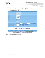
Страница 225: ... within Internet but user can login RS 2500 remotely and enable Wake on Lan function to boot up the LAN computer Configuration Example Wake On Lan STEP 1 Select Setting in Wake on Lan and enter MAC Address to specify the computer who needs to be booted up remotely User can press Assist to obtain the MAC Address from the table list Figure 22 31 Figure 22 31 Wake on Lan Setting STEP 2 User only need...

Страница 226: ...splay the Maximum Downstream Upstream Bandwidth of that WAN set from Interface Downstream All tage of Downstream according to WAN traffic ffic PPPoE Con Time The last time of the RS 2500 to be enabled MAC Address The MAC Address of the Interface IP Address tmask of the Interface Default Gateway To display the Gateway of WAN DNS1 2 The DNS1 2 Server Address provided by ISP Rx Tx Pkts Error Pkts To ...

Страница 227: ...ication user IP The login time of the user Status Authentication Enter Authentication in Status function it will display the record of log Figure 22 34 IP Address Th Auth User Name The account of the auth user to login Login Time Year Month DayHour Minute Second Figure 22 34 Authentication Status WebUI ...

Страница 228: ...ut IP Address MAC Address and the Interface information which is connecting to the RS 2500 Figure 22 35 Anti ARP virus software Works to rewrite LAN ARP table as default IP Address The IP Address of the network MAC Address The identified number of the network card Interface The Interface of the computer Figure 22 35 ARP Table WebUI ...

Страница 229: ...IP Start End Figure 22 36 DHCP Clients WebUI STEP 1 In DHCP Clients of Status function it will display the table of DHCP Clients that are connected to the RS 2500 Figure 22 36 IP Addre MAC Address The IP that corresponds to the dynamic IP Leased Time The valid time of the dynamic Year Month Day Hour Minute Second ...

Страница 230: ... 2 Question Why I reboot RS 2500 the time setting will be reset to default setting Answer RS 2500 is not built in with battery so it can not save the data permanently and that is reason why the time will be reset to default every time you reboot the device So you can configure NTP server function for RS 2500 to refresh time when it boot up but you have to make sure in advance that the WAN port of ...

Страница 231: ...dwidth of User Group A does not reach to QoS limitation so it will have roup B th no matter the priority uestion How bandw nswer Simp the QoS priority function of RS series gateway syste idth iority of QoS works to allow user o ly For example the line speed is 512 256 Kbps downstream upstr 2 128 64 Kbps the priority is middle So there is 128 64 Kbps bandwidth is free Presume the User Group A was a...

Страница 232: ...efault port for authentication is port 82 Therefore please type the following int The gateway s loca your username and password Th service you just need to open you s can access the web normally I did configure Authentication setting but why the client user can access Internet without passing authentication Please check Outgoing Polic rule you need to create another ru and the rule must move to th...

Страница 233: ...pe I can use to connect Web SSL VPN Windows IE FireFox Safari and Google Chr A Question Why I can not access Web SSL VPN correctly Answer The reason could be related to java program You can try to do following things before to connect Web SSL VPN 1 Clean browser s temporary file 2 Uninstall java program download and install the latest version java software system will download java program to clie...

Страница 234: ...hield RJ 45 Ethernet UTP port 2 10 100 Support xDSL Cable Leased Line Service WAN port Modify the MAC address Shield RJ 45 Ethernet UTP port 1 10 100 DMZ port Modify the MAC address Factory Reset B utton Dimensions W x D x H cm 22 0 x 15 0 x 4 0 Size Desktop Weight Kgs 0 94 Power DC 5V 2 4A Performance WAN LAN Zone 1 Zone 2 Port 1 Port 2 100 Mbps 3DES Encryption 35 Mbps Throughput VPN SSL VPN 10 M...

Страница 235: ...inistrator Max entry 10 Remote Monitor Web Management Port Number can be changeable Permitted IPs Max entry 32 Web UI Logout Remote management MTU changeable for WAN Interface Statistics Traffic Statistics WAN Policy Multiple Subnet NAT Routing NAT Max entry 16 Route Table Max entry 10 Dynamic Routing RIPv2 Host Table Max entry 20 DDNS Max entry 16 Save configuration to files Load configuration fr...

Страница 236: ...ction Load balancing O Auto AI Mode By Session By ure IP By Destination IP utBound Packet Round Robin Auto Backup By Sec I CMP WAN Port connection status D NS VPN Function One Step IPSec IPSec Dead Peer Detection Show remote Network Neighborhood IKE SHA 1 MD5 Authentication IPSec Autokey E ISAKMP Auto Key management via IK IPSec Max entry 200 100 PPT 32 32 P Server Max entry Allow to Configure Con...

Страница 237: ...vers 4 Virtual Server Service Name Max entry 16 Virtual Server Multi Servers Load Balancing 4 SPI Stateful Pa cket Inspection MAC Address Filtering Assign WAN Link by Source IP Assign WAN Link by Destination IP Assign WAN Link by Port Packet Filtering by Source IP Packet Filtering by Destination IP Packet Filtering by Port Access y grou control b p Time Schedul Manageme e nt Max Concurr nt Session...

Страница 238: ...rar iso bin rpm pdf tgz gz bat com dll hta scr s pif com msi reg mp3 mpeg mpg Upload Blocking doc xl ppt Extensions vb wp Auto Update Definitions 30 min eDonkey BT WinMX Foxy KuGoo AppleJuice AudioGalaxy DirectConnect iMesh MUTE Thunder5 P2P Blocking VNN Client MSN Messenger Yahoo Messenger ICQ QQ Skype VoIP Google Talk IM Blocking Gadu Gadu IM P2P Blocking IM P2P Rule Drop Intruding Packets Traff...

Страница 239: ...reas telephone c 100Base TX 802 3u The IEEE standard defines how to transmit Fast Ethernet 100Mbps data using Cat 5 UTP STP cab 100Base TX standard is backward compatible with the 10Mbps 10 BaseT standar WAN Wide Area Netwo m cation system of connecting PCs and other computing devices across a large local regional national or international geographic are LAN It is a computer network covering a sma...

Страница 240: ...ddress assigned to it by DHCP server A DHCP server can ither be a designated PC on the network or another network device such as router program that translates URLs to IP addresses by accessing a database maintained on a ollection or Internet servers ynamic Domain Name System An Algorithm that allows the use of dynamic IP address r hosting Internet Server DDNS service provides each user account wi...

Страница 241: ... data TCP takes care of keeping f the packets that a message is divided into for efficient routing through the Internet DP ser Datagram Protocol A layer 4 network protocol for transmitting data that does not acknowledgement from the recipient of the data Subnetw Found in larger networks these smaller networks are used to simplify addressing between numerous computers Subnets connect to the central...

Страница 242: ...n Router can use bandwidth control to limit the Internet connection speed of individual IP or Application It can also guarantee the speed of certain special application or privileged IP addr s RADIUS Remote Authentication Dial In User Service An authentication and accounting system used by many Internet Service Providers ISPs When you dial in to the ISP you must enter your username and password Th...

Страница 243: ... using the Windows PPTP client the remote VPN server must support PPE Microsoft Point To Point Encryption Protocol encryption PPTP is also used by ome ISP for user authentication particularly when pairing with legacy Alcatel Thomson DSL modem reshare Key he IKE VPN must be defined with a Preshared Key The Key may be up to 128 bytes long c SSL Security Sockets Layer Commonly used encryption scheme ...

Страница 244: ... digest hash algorithm that takes a message less than 264 bits and produces a ISAKMP Inte frame AH Authentication Header One of the IPSec standards ESP One of the IPSec standards that provides for the confidentiality of data packets DES Data Encryption Standard The Data Encryption Standard developed by IBM c Triple DES 3DES The DES function performed three times with either two or three cryptograp...

Страница 245: ...ec T 25 4 Anomaly Flow IP asser computers running vulnerable versions of the Thus it particularly virulent in that it can spread without user intervention but it is also easily topped by a properly configured firewall or by downloading system updates from Windows wn as Lovsan or Lovesan was a computer worm that spread n computers running the Microsoft operating systems Windows XP and Windows 2000 ...

Страница 246: ...s a computer worm and is also a file infector It quickly spread eclipsing the economic damage caused by past outbreaks suc ectors allowed Nimda to become the Internet s most widespread virus worm within 22 v m SYN Flood A SYN flood is a form of denial of service attack in which an attacker sends a S ICMP Flood A smurf attack is on re o machine The network then serves as a sm perpetrators will send...

Страница 247: ...omputers and vulnerable ports that are opened by those computers T T length Some data into the System to cause System damage such as a shut down or a restart Detect Land Some Systems may shut down when receiving packets with the same source and destination addresses the same source port and destination port and when SYN on the TCP header is marked Enable this function to detect such abnormal packe...

Отзывы: