background image

8

Opening the DRN-STN

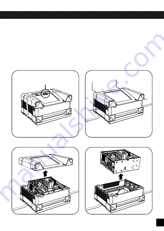
To open the DRN-STN

Place the DRN-STN on a clean and smooth

surface with its front side facing down.

1)  Release the Belt Buckle (BB)

2)  Open the 4 Butterfly Latches (BL)

3)  Lift and remove the back cover

4)  Take out the chassis.

BL

BL

BL

BL

BB

1)

2)

3)

4)

Содержание DRN-STN

Страница 1: ......

Страница 2: ...es 6 Opening Butterfly Latches 7 Opening the DRN STN 8 System integration 9 17 Cable Outlet 15 Power on Reset 18 Monitor adjustment 19 Fan speed adjustment 20 Dust Filter removing 21 Dust Filter placement 22 Security 23 Product specs 24 26 Warranty 26 ...

Страница 3: ...nings The length of the expansion cards in position 1 2 3 may be maximum 425 mm The length of the expansion cards in position 4 5 6 7 may be maximum 285 mm The height of the CPU cooler may be maximum 140 mm ...

Страница 4: ...on of the 6 Housing Fans together may be maximum 30 watt Housing airflow Do NOT block the air inlet at the left side of the DRN STN Do NOT block the air outlet at the top side of the DRN STN Do NOT block the air outlet at the right side of the DRN STN This is to ensure proper cooling of all electric components inside the DRN STN 6 fans together 30 watt ...

Страница 5: ...upply Unit PSU must NOT face the chassis wall The air inlet of the Power Supply Unit PSU must face the inside of the chassis The air inlet of the Power Supply Unit PSU must be free from obstructions to ensure proper cooling of the PSU Warnings ...

Страница 6: ...ottom Grip Left Bottom Grip Right Main Power In Socket C14 Local Area Network Socket RJ45 USB2 0 24 inch Monitor 5 25 inch Bays Monitor Buttons Fan Speed Switches USB3 0 Power Button Reset Button Microphone Socket 3 5 mm Headphone Socket 3 5 mm 5 ...

Страница 7: ...doff M1 1 x MB Mounting Standoff Tool T1 2 x 5 25 Device Mounting Part L P1 2 x 5 25 Device Mounting Part R P2 16 x 3 5 Device Mounting Part P3 6 x Tie wrap W1 1 x Buzzer B1 1 x Padlock Loop L1 1 x Chassis Molex cable C2 1 x Chassis User Interface cable C3 Inside the Accessory Box you will find the following parts ...

Страница 8: ...he latch Make sure the latch overlaps the hook on the back cover 5 Rotate the grip 180 degrees clockwise 6 Push the grip so it comes flat To open a Butterfly Latch 1 Lift the grip 2 Rotate the grip 180 degrees counter clockwise 3 Lift the latch by pulling the grip 1 2 3 ...

Страница 9: ...he DRN STN Place the DRN STN on a clean and smooth surface with its front side facing down 1 Release the Belt Buckle BB 2 Open the 4 Butterfly Latches BL 3 Lift and remove the back cover 4 Take out the chassis BL BL BL BL BB 1 2 3 4 ...

Страница 10: ...ings A B C to guide and hide cables at its backside 4 For mounting cables the backside of the motherboard plate offers 22 Mounting Loops ML With the use of Tie wraps W1 cables can be attached to these loops Installing the motherboard 1 Please read the manual of your motherboard for the location of the motherboard mounting holes 2 Use the Motherboard Mounting Standoff Tool T1 to screw the Motherboa...

Страница 11: ...ips into the 3 5 mounting bracket until it snaps firmly in place 3 Please read the manual of your motherboard 3 5 device to connect the power and data cables Installing a 2 5 device 1 One 2 5 device can be mounted with 4 screws S2 to the bottom side of the chassis 2 Please read the manual of your motherboard 2 5 device to connect the power and data cables P3 S2 ...

Страница 12: ...ctors of the Chassis Fans to the motherboard In case your motherboard only offers one fan connector check the motherboard manual if you can use a separate splitter to connect both Chassis Fans Note the fan speed of the two Chassis Fans inside the chassis can only be controlled by the motherboard BIOS The DRN STN has no switches for Chassis Fan speed adjustment ...

Страница 13: ...he add on cards will be installed 4 Use a flat screw driver to break out the strip s to create openings for the add on card s Be careful not to damage the motherboard or other components 5 Follow the installation instructions in the manual s of your add on card s Optionally you can mount the add on card s with a screw s S3 6 To lock the add on cards rotate the add on card mounting clamp handle 90 ...

Страница 14: ... of the 5 25 Device Mounting Parts into the square holes at the bottom side of the chassis 3 Mount both 5 25 Device Mounting Parts with screws S3 to the bottom of the chassis Please read the manual of your motherboard 5 25 device to connect the power and data cables Guide the power and data cables through the oval shaped holes at the bottom side of the chassis 4 Remove the corresponding 5 25 blank...

Страница 15: ...e Chassis PCB CP inside the chassis Connecting the Chassis User Interface cable 1 Plug the 10 pin connector of the Chassis User Interface cable C3 to the Chassis PCB CP inside the chassis Make sure you plug it in the right way it fits only in one orientation 2 Please read the manual of your motherboard before you connect the connectors on the other end of the Chassis User Interface cable to the re...

Страница 16: ...This is to prevent the cables from being trapped under the chassis Cable Outlet At the bottom side of the DRN STN housing next to the Main Power In Socket there is an outlet for cables If you want to connect an external device to the motherboard or add on card such as a speaker set or a second monitor the cable of the device can be guided through this opening ...

Страница 17: ...y Unit Note in case the Power Supply Unit has an on off switch make sure you switch it on for safety please check the PSU manual Please read the manual of your motherboard add on cards before you connect the cables of the DRN STN to the motherboard add on card s 4 Plug the USB2 0 connectors H4 round cables to the motherboard 5 Plug the USB3 0 connectors H5 flat cables to the motherboard 6 Plug the...

Страница 18: ...over on the DRN STN and lock the 4 Butterfly Latches Connect the power cord connector C13 to the Main Power In Socket C14 of the DRN STN In case you have a wired LAN connection connect the LAN RJ45 connector to the LAN Socket of the DRN STN ...

Страница 19: ...ress the PWR button for 1 second The LED s behind all the buttons will light up to their maximum intensity for 20 seconds After 20 seconds the light intensity will dim down to 50 of the maximum Reset To reset the DRN STN press the RST button for 1 second ...

Страница 20: ...edly to scroll through the menu and select the item you want to adjust the selected item will be highlighted 3 Use the Up or Down V buttons to adjust the value of the selected item change settings 4 After adjustment s press the MENU button several times until you reach EXIT then press either the Up or Down V button to close the On Screen Display ...

Страница 21: ...er fan speed adjustments 2 Air exhaust adjustment To adjust the speed of the Exhaust Fans right side of the DRN STN slide the R switch to the required position 3 means the fan speed is 100 2 means the fan speed is 66 1 means the fan speed is 38 It is recommended to set the switch to 3 100 If you would like to reduce the noise level you can reduce the fan speed to 2 or 1 Always monitor the temperat...

Страница 22: ...the LAN socket are mounted 3 Lay down the 3 fans Make sure you do not damage unplug their wires 4 Remove the 3 metal wires that hold the Dust Filter 5 Take out the Dust Filter Clean the Dust Filter with a vacuum cleaner and or wash it in warm but not hot water It is recommended to clean the Dust Filter regularly The frequency of cleaning depends on the cleanness of the environment in which the DRN...

Страница 23: ...ean place it back in its compartment 2 Place the 3 Metal Wires that hold the Dust Filter back in their original position 3 Place the 3 Intake Fans back in their original position 4 Mount the fans with their original 6 screws See page 15 for placing the chassis inside the DRN STN housing ...

Страница 24: ...ed The cable of the Kensington lock can go out of the DRN STN through the Cable Outlet at the bottom of the chassis Padlock loop The padlock loop L1 can be mounted to the chassis with one screw S3 Slide the padlock loop from the inside through the opening in the back of the chassis and add the screw L1 S3 ...

Страница 25: ...ling Left side 3 x 12 cm fans air in fans included Top side 2 x 12 cm fans air out fans included Right side 3 x 12 cm fans air out fans included Optional fans Chassis air in 2 x 12 cm fans extra not included Chassis air out 1 x 12 cm fan extra not included Replacing 2 x 12 cm topside fans by 2 x 14 cm fans not included Fan spec 120 x 120 x 25 mm Fan LED color Blue optional Green or Red Sleeve bear...

Страница 26: ...TCO 5 1 Pixel class A User interface front side Menu button Adjust buttons Buttons LED back light color White Monitor Model B Brand AUO Optical Response Time 12 ms black white Typ on off Vertical Refresh Rate 60 Hz LCD Type TN LCD Backlight LED Diagonal 609 7 mm 24 inch Maximum resolution 1920 x 1080 Full HD Aspect ratio 16 9 Colors 16 7 Million RGB 6 bit Contrast ratio 3 000 1 Brightness 250 cd m...

Страница 27: ... been removed 2 The product has been modified or altered In case of conflict between the warranty provided by the country of point of sale and this manual the warranty of the actual country of point of sale will prevail In case of malfunction of electronic components or need of accessories purchase during the warranty period please return the DRN STN to the original store of purchase Warranty Moni...

Страница 28: ...an e mail sales aio group com AIO Europe BV Kiotoweg 70E 3047BG Rotterdam The Netherlands Tel 31 10 7528150 e mail sales aioeurope nl AIO China 2 6TH Floor NO 603 Sanzheng Shiji Haoting Qing Hu Tou TangXia Town DongGuan City Guangdong China Tel 86 769 82080123 e mail china aio group com ...

Отзывы: