26
Trivet
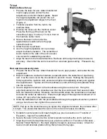
Manhole Base Set-up
1.
Prepare the laser for use: Attach handle/rod
mount, apply power, center the line
adjustment, and enter desired grade. Mount
the height adjustable rod (center the rod
height in its adjustment range) to the trivet.
(Figure J)
2.
Transfer elevation from the hub to the
manhole base.
3. Position the trivet over the manhole center:
Place the front leg of the trivet on the
centerline-of-pipe, 5 inches (13 cm) in front of
the manhole center mark.
4. Secure the laser to the rod at the
approximate elevation where the pipe
centerline will be.
5. Allow the unit to self level.
6. Use the height adjustable rod to precisely
adjust the beam elevation. The centerline of
beam marks on the side of the unit are also
convenient for establishing elevation.
7.
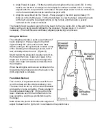
Align the beam to the forward manhole. Recheck all the alignment steps to assure
accuracy. Check that the unit is level with an accurate grade setting. Proceed to lay
pipe.
Rod and Crossbrace System
1. Prepare the laser for use: Attach handle/rod mount, apply power, and center the line
adjustment.
2. Mount crossbrace inside the manhole, perpendicular to the centerline of pipe being
laid. Use the level vial on the crossbrace ro position it level. Holding the two points
firmly against the manhole wall, extend and tighten the adjusting screw point against
the opposite wall. Tighten until the crossbrace is solid, with the points planted firmly
into the concrete.
3. Secure alignment element to the crossbrace using the secure knob. Hang the
alignment element on the crossbrace so that the line control and front secure knobs
face the forward manhole. Measure manhole width where the crossbrace is mounted
and use the center as reference. Place the right edge of the alignment element 2-1/4
inches (57 mm) left of the manhole center.
4. Slide the calibrated rod with the point attached through the alignment element, plumb it
using a hand level, then tighten the secure knob.
NOTE: Pull up on the crossbrace as you tighten the alignment element, then release after
it is tight. This places downward tension on the rod and increases its stability.
5. Establish invert elevation and beam height (see previous section on “Transfer of
Elevation – Special Transit Method”).
6. Secure the laser to the rod at the correct elevation and allow the unit to self-level.
7. Align beam to the forward manhole (see previous section on “Transfer of Elevation –
Special Transit Method”). Recheck alignment steps to assure accuracy. Check for
level unit and accurate grade setting, then proceed to lay pipe.
Содержание GradeLight 3000
Страница 1: ...GradeLight 3000 Pipe Laser ...
Страница 4: ...3 Laser Overview ...
Страница 38: ...37 ...
Страница 39: ...38 ...
Страница 40: ...39 Printed in USA AM1145 3 10 Specifications subject to change without notice ...


