40
Chapter 2
Basic Operation
Configuring the RF Output
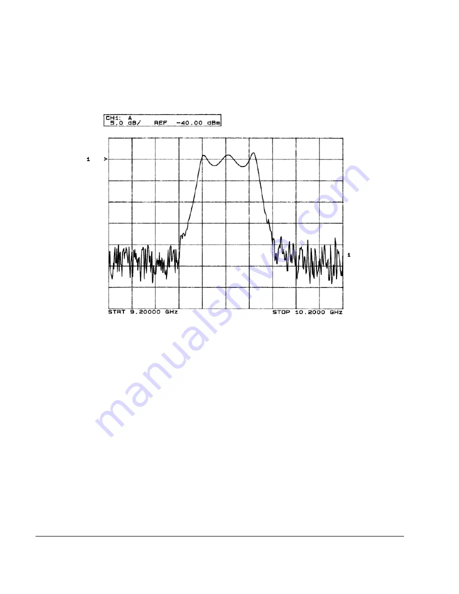
Figure 2-3
Bandpass Filter Response on 8757D
Using Markers
1. Press
Markers
.
This opens a table editor and associated marker control softkeys. You can use up to 10 different markers,
labeled 0 through 9.
2. Press
Marker Freq
and select a frequency value within the range of your sweep.
In the table editor, notice how the state for marker 0 automatically turns on. The marker also appears on
the 8757D display.
3. Use the arrow keys to move the cursor in the table editor to marker 1 and select a frequency value within
the range of your sweep, but different from marker 0.
Notice that marker 1 is activated and is the currently selected marker, indicated by the marker arrow
pointing down. As you switch between markers, using the arrow keys, you will notice that the selected
marker’s arrow points down, while all others point up.
Notice also that the frequency and amplitude data for the currently selected marker is displayed on the
8757D.
Содержание E8247C
Страница 10: ...Contents x ...
Страница 96: ...86 Chapter 4 Analog Modulation Configuring the LF Output ...
Страница 127: ...Chapter 5 117 Dual Arbitrary Waveform Generator Using Waveform Clipping Figure 5 16 Rectangular Clipping ...
Страница 128: ...118 Chapter 5 Dual Arbitrary Waveform Generator Using Waveform Clipping Figure 5 17 Reduction of Peak to Average Power ...
Страница 142: ...132 Chapter 6 Custom Arb Waveform Generator Working with Filters ...
Страница 178: ...168 Chapter 7 Custom Real Time I Q Baseband Working with Differential Data Encoding ...
Страница 198: ...188 Chapter 10 Troubleshooting ...
Страница 214: ...204 Chapter 10 Troubleshooting Returning a Signal Generator to Agilent Technologies ...


