


4
SAFETY SUMMARY (continued)
GENERAL
Any LEDs used in this product are Class 1 LEDs as per IEC 825-l.
ENVIRONMENTAL CONDITIONS
This instruments is intended for indoor use in an installation category II, pollution degree 2 environment. It is designed to
operate at a maximum relative humidity of 95% and at altitudes of up to 2000 meters. Refer to the specifications tables for
the ac mains voltage requirements and ambient operating temperature range.
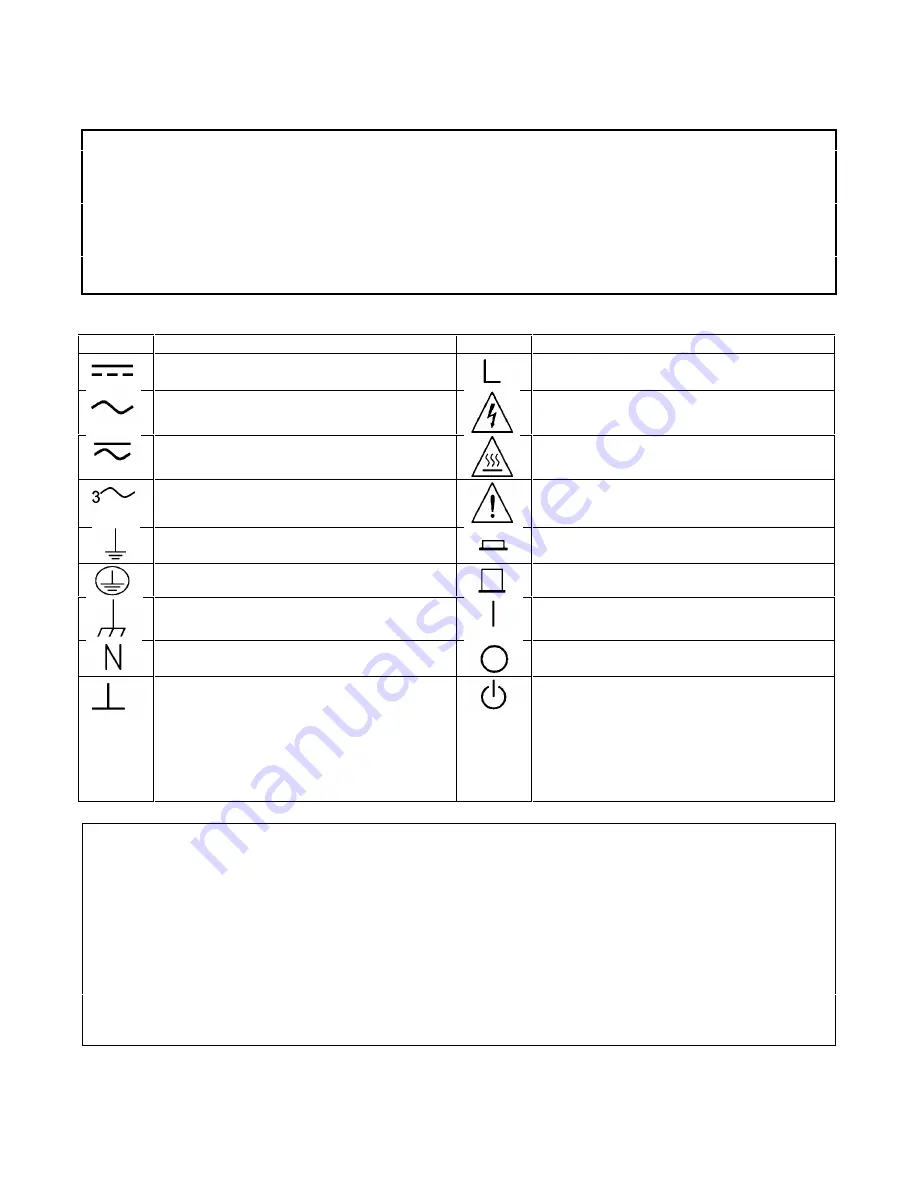
SAFETY SYMBOL DEFINITIONS
Symbol
Description
Symbol
Description
Direct current
Terminal for Line conductor on permanently
installed equipment
Alternating current
Caution, risk of electric shock
Both direct and alternating current
Caution, hot surface
Three-phase alternating current
Caution (refer to accompanying documents)
Earth (ground) terminal
In position of a bi-stable push control
Protective earth (ground) terminal
Out position of a bi-stable push control
Frame or chassis terminal
On (supply)
Terminal for Neutral conductor on permanently
installed equipment
Off (supply)
Terminal is at earth potential(Used for
measurement and control circuits designed to
be operated with one terminal at earth
potential.)
Standby (supply)
Units with this symbol are not completely
disconnected from ac mains when this switch is
off. To completely disconnect the unit from ac
mains, either disconnect the power cord or
have a qualified electrician install an external
switch.
Herstellerbescheinigung
Diese Information steht im Zusammenhang mit den Anforderungen der Maschinenläminformationsverordnung vom 18
Januar 1991.
* Schalldruckpegel Lp <70 dB(A) * Am Arbeitsplatz * Normaler Betrieb * Nach EN 27779 (Typprufung).
Manufacturer’s Declaration
This statement is provided to comply with the requirements of the German Sound Emission Directive, from 18 January
1991.
* Sound Pressure Lp <70 dB(A) *At Operator Position * Normal Operation * According to EN 27779 (Type Test).
Содержание 6050A
Страница 10: ......
Страница 14: ......
Страница 32: ......
Страница 46: ...46 Installation Figure 3 12 Local Sensing Figure 3 13 Remote Sensing...
Страница 47: ...Installation 47 Figure 3 14 Parallel Operation Figure 3 15 Zero Volt Loading...
Страница 48: ......
Страница 55: ...Local Operation 55 Figure 4 2 Recommended Programming Sequence...
Страница 64: ......
Страница 69: ...Remote Operation 69 Figure 5 1 Remote Programming Flowchart Sheet 1...
Страница 70: ...70 Remote Operation Figure 5 1 Remote Programming Flowchart Sheet 2...
Страница 74: ......
Страница 78: ...78 Calibration Figure 6 2 Calibration Flowchart for A Modules...
Страница 79: ...Calibration 79 Figure 6 2 Calibration Flowchart for A Modules continued...
Страница 80: ...80 Calibration Figure 6 2 Calibration Flowchart for A Modules continued...
Страница 85: ...Calibration 85 Figure 6 3 Calibration Flowchart for B Modules...
Страница 86: ...86 Calibration Figure 6 3 Calibration Flowchart for B Modules continued...
Страница 87: ...Calibration 87 Figure 6 3 Calibration Flowchart for B Modules continued...


