background image

34

User Manual

4

Instrument Connection

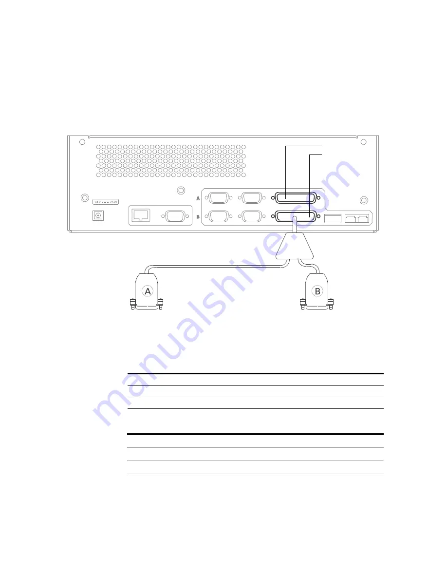
Figure 9

Digital I/O cables

B

A

INSTR PORT

RS-232

LAN

B

A

REMOTE

DIGITAL I/O

ANALOG

See 

Table 9

 for digital I/O cables

See 

Table 10

 for bottle number cables

Digital I/O Adaptor Cable 


Agilent part number 35900-60960

Channel A
Channel B

Table 9

Digital I/O cables 

Part no.

Description

Refer to

35900-60670

General purpose spade lugs (2 m)

Figure 20

 on page 54

35900-60920

General purpose spade lugs (5 m)

Figure 20

 on page 54

Table 10

Bottle number cables 

Part no.

Description

Refer to

35900-60670

General purpose spade lugs (2 m)

Figure 22

 on page 56

35900-60920

General purpose spade lugs (5 m)

Figure 22

 on page 56

Содержание 35900E Series II

Страница 1: ...Agilent Technologies Agilent 35900E Series II Dual Channel Interface User Manual...

Страница 2: ...ied warranties of merchantability and fitness for a par ticular purpose Agilent shall not be liable for errors or for incidental or consequential damages in connec tion with the furnishing use or per...

Страница 3: ...tion 10 Front Panel 10 Start Stop push buttons 10 Run status indicators 10 Hardware monitoring indicators 11 Important Safety Warnings 11 Electrostatic discharge is a threat to 35900E Series II electr...

Страница 4: ...munications 25 To connect RS 232 communications 25 4 Instrument Connection Analog Input Signal Connection 28 Remote Control Connection 30 Digital I O Connection 33 Instrument Control Port Connection 3...

Страница 5: ...User Manual 5 7 Instrument Parts Replacement Parts Covers and Electronics 48 Power Cords 50 A Cables Analog Signal Cables 52 Remote Control 54 APG Remote Control 55 Bottle Number Cables 56...

Страница 6: ...6 User Manual...

Страница 7: ...ications 12 Cleaning 14 Recycling the Product 14 The Agilent 35900E Series II Dual Channel Interface 35900E Series II is a dual channel run buffered interface that connects analytical instruments to A...

Страница 8: ...o independent analog to digital A D converters or dual channel synchronous Real time control Instrument control ports Host communication Front panel indicators that show run status interface activity...

Страница 9: ...lexing or the sampling process Real Time Control The 35900E Series II provides a set of real time control functions for a host computer system These can be separated into two groups Remote Control Bus...

Страница 10: ...tors for each channel There are also four indicator LED indicators at the bottom of the panel to convey general information about the state of the 35900E Series II interface Start Stop push buttons Ea...

Страница 11: ...ar a grounded wrist strap any time you must access the 35900E Series II internal components Table 1 LED monitoring indicators for the 35900 Series II LED Indicator LED Color Description ACTIVE Yellow...

Страница 12: ...ce is designed and manufactured under a quality system registered to ISO 9001 Information The Agilent 35900E Series II Dual Channel Interface meets the following IEC International Electro technical Co...

Страница 13: ...rds of design and the intended use of the instrument Agilent Technologies assumes no liability for the customer s failure to comply with these requirements See accompanying instructions for more infor...

Страница 14: ...radio or antenna 2 Move the device away from the radio or television 3 Plug the device into a different electrical outlet so that the device and the radio or television are on separate electrical cir...

Страница 15: ...nnel Interface User Manual Agilent Technologies 2 Setup To Unpack the Unit 16 Checking Parts and Accessories 16 Line Voltage 16 Configuration Switch 17 This section provides procedures for unpacking a...

Страница 16: ...he carton and all packing materials for the carrier s inspection Contact your nearest Agilent Technologies Sales and Service Office immediately Checking Parts and Accessories 1 Verify that you have al...

Страница 17: ...switches on the rear panel that control 35900E Series II operation The default settings are shown in Figure 2 Table 2 describes the individual switch settings Figure 2 Configuration switch and default...

Страница 18: ...Up Causes an audible beep when Start Stop is pressed Down Silent at Start Stop 2 HI LO Up Beep if any is loud Down Beep if any is soft 3 Channel A TEST NORM Up Selects stored test chromatogram Analog...

Страница 19: ...chnologies 3 Computer Connection Connecting to a TCP IP Network 20 Configuring an RS 232 Connection 22 Connecting to a Host Computer Using RS 232 Communications 25 The 35900E Series II supports TCP IP...

Страница 20: ...0 to both the 35900E Series II and network before turning on the 35900E Series II To communicate with the 35900E Series II you must assign it an IP address compatible with the site LAN The 35900E Seri...

Страница 21: ...set the instrument IP address you can restore the default IP address and enable DHCP as follows 1 Turn off the instrument 2 While pressing and holding the STOP key turn on the instrument Hold the STOP...

Страница 22: ...ility The RS 232 connection has a single 8 position configuration switch on the inside of the 35900E Series II see Figure 4 To access the 8 position configuration switch you must remove the top cover...

Страница 23: ...3 set to OFF indicates software handshaking Switch 4 set to ON enables parity checking Switch 5 set to OFF indicates odd parity Switches 6 through 8 combine to indicate baud rate See Table 4 for switc...

Страница 24: ...on Install the top cover when finished Table 4 Example settings for RS 232 baud rates Switch Baud rate 6 7 8 300 OFF OFF OFF 600 OFF OFF ON 1200 OFF ON OFF 2400 OFF ON ON 4800 ON OFF OFF 9600 ON OFF O...

Страница 25: ...n page 20 Only one host connection can be made to a host computer at a time To connect RS 232 communications 1 Power off the 35900E Series II and the host computer 2 Connect one end of the cable to th...

Страница 26: ...26 User Manual 3 Computer Connection...

Страница 27: ...Instrument Connection Analog Input Signal Connection 28 Remote Control Connection 30 Digital I O Connection 33 Instrument Control Port Connection 36 This section provides the analog signal remote cont...

Страница 28: ...Turn off the power to the instrument supplying the analog output signal 2 For instrument specific cables Connect one end of the cable to the instrument s analog output using the instrument manufactur...

Страница 29: ...0 6890 6850 Gas Chromatograph GC 6 pin 2 m Figure 17 on page 52 35900 60570 5880 GC Figure 18 on page 52 35900 60630 General purpose spade lugs 12 m Figure 17 on page 52 35900 60900 General purpose sp...

Страница 30: ...all open cables Figure 8 Remote control connection B A INSTR PORT RS 232 LAN B A REMOTE DIGITAL I O ANALOG Channel A Channel B Table 6 Remote control cables Part no Description 35900 60610 5890 Remot...

Страница 31: ...ent s remote control contacts See also Table 8 on page 32 The following notes apply to a general purpose connection START and STOP lines are used for both input and output As input a 10 ms or longer p...

Страница 32: ...ple leak stop pump 5 Reserved 6 Power On High level indicates that all instruments connected to the system are switched on 7 Ready High level indicates that system is ready for next analysis sequence...

Страница 33: ...d in Table 9 or Table 10 Appendix A lists pin assignments for all open cables 1 Turn off the power to both the 35900E Series II and the instrument containing the digital I O connections 2 Attach the Y...

Страница 34: ...Agilent part number 35900 60960 Channel A Channel B Table 9 Digital I O cables Part no Description Refer to 35900 60670 General purpose spade lugs 2 m Figure 20 on page 54 35900 60920 General purpose...

Страница 35: ...of the 35900E Series II 3 For instrument specific cables Connect one end of the cable to the instrument s digital I O connector using the instrument manufacturer s instructions For general purpose cab...

Страница 36: ...0980 for RS 232C communication to a 5890 GC or 7673 Sampler Attach one end of the RS 232C cable to the channel A or B instrument port and the other end to the instrument Figure 10 RS 232C connection f...

Страница 37: ...User Manual Agilent Technologies 5 Startup Pre Run Checklist 38 35900E Series II Power Up 38 Verify 35900E Series II is Ready for Operation 39 In Case of Difficulty 40 This section provides steps to...

Страница 38: ...to host computer or network Analog signal cables connected Remote control cables connected if needed Digital I O cables connected if needed Power cord connected 35900E Series II Power Up Power up the...

Страница 39: ...No other indicators are blinking If the red FAULT LED is blinking about once per second the 35900 Series II is configured for DHCP and the external computer has not provided an IP address Check the ex...

Страница 40: ...that causes the failure Replace the cable If the problem persists after cycling the power note the LED pattern on the front panel display Check Table 11 for possible causes for failure If the fault c...

Страница 41: ...le parts inside the 35900E Series II The 35900E Series II was designed for easy assembly and disassembly of all the replaceable modules The only tool needed for this process is a PoziDriv screwdriver...

Страница 42: ...the frame slipping the front tabs under the front panel edge 7 Push the cover firmly down and towards the front until the screw holes are aligned and the back flaps are flush with the back of the unit...

Страница 43: ...onnector see Figure 12 WARNING This procedure is intended for use by Agilent trained service personnel only There are no user serviceable parts inside the 35900E Series II CAUTION The printed circuit...

Страница 44: ...p of the frame and push it against the frame fitting the power switch into the hole 7 Replace the four screws two on each side see Figure 13 above 8 Connect the front panel cable to the connector pres...

Страница 45: ...he Front Panel on page 43 3 Disconnect the power cable 4 Remove the three screws attaching the main board on the back of the unit Figure 14 WARNING This procedure is intended for use by Agilent traine...

Страница 46: ...all the main board 1 When you are ready to install the main board slide the main board into the guides from the front of the unit so that the cable connections fit through the back of the unit 2 Repla...

Страница 47: ...eries II Dual Channel Interface User Manual Agilent Technologies 7 Instrument Parts Replacement Parts Covers and Electronics 48 Power Cords 50 This section provides diagrams for instrument parts of th...

Страница 48: ...ronics Table 12 Replacement parts for the 35900E Series II Figure 16 Item no Description Part no Qty 1 Top cover 35900 01180 1 2 24V DC power converter 0950 4789 1 3 Main board 35900 61000 1 4 Front p...

Страница 49: ...Instrument Parts 7 User Manual 49 Figure 16 Replacement parts breakdown 1 2 3 4 5...

Страница 50: ...amp 8120 3997 Power cord Denmark Greenland C13 10 amp 8120 4211 Power cord India South Africa C13 10 amp 8120 4753 Power cord Japan C13 125 volt 8120 5182 Power cord Israel C13 10 amp 8120 6869 Power...

Страница 51: ...e User Manual Agilent Technologies A Cables Analog Signal Cables 52 Remote Control 54 Bottle Number Cables 56 This section provides cable diagrams for the open analog signal remote control and bottle...

Страница 52: ...ction Figure 17 35900 60630 35900 60900 35900 60910 General use spade lugs Connector 1 Signal name Connector 2 1 Shield Orange 2 Signal Black 3 Signal Red Figure 18 35900 60570 5880 GC 35900 60750 105...

Страница 53: ...Cables A User Manual 53 Figure 19 35900 60640 For special purpose square pins Connector 1 Signal name Connector 2 1 Shield Orange 2 Signal Black 3 Signal Red 1 2 3...

Страница 54: ...mote signal 1 Black GND 2 White Prepare 3 Red Start 4 Green Shut Down 5 Brown Reserved 6 Blue Power On 7 Orange Ready 8 Yellow Stop 9 Violet Start Request Black tubing Shield Note When used for remote...

Страница 55: ...ncluded in this section Figure 21 G1530 60930 APG Remote control cable pin assignments Connector 1 male Signal name Connector 2 male 1 GND 1 2 Prepare 2 3 Start 3 4 Start relay 4 5 Start relay 5 6 No...

Страница 56: ...60920 Bottle number cable diagram Connector 1 Connector 2 Remote signal 1 Black Ground 2 White Binary Code Decimal BCD 1 3 Red BCD 2 4 Green BCD 4 5 Brown BCD 8 6 Blue BCD 80 Note When used for remot...

Страница 57: ...ubing Shield Connector 1 Connector 2 Remote signal Note When used for remote control this cable attaches directly to remote port on back of 35900E Series II When used for digital I O or bottle numbers...

Страница 58: ...Agilent Technologies Agilent Technologies Inc Third edition October 2017...

Отзывы: