Agilent Technologies 1660A Series Скачать руководство пользователя страница 57

3

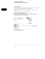
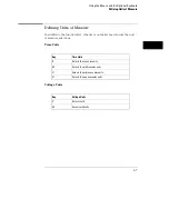
Using the alpha keypad, enter a custom name as shown below.

A custom name can contain up to 10 letters.  As you type the new name, the
old name is overwritten.

Alpha Entry

4

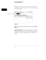
When you are finished entering a custom name, press the 

Done

 or

Select

 keys.

Changing Alpha Entries

If you want to make changes or corrections

in the alpha entry field, use the arrow keys or the knob to position the
underscore marker under the character you want to change and type the
new letters.  To quickly clear the Name field, you can press the Clear
entry key.

Name field

Using the Front-Panel Interface

How to Enter Alpha Data

3–22

Содержание 1660A Series

Страница 1: ...edition January 2000 For Safety information Warranties and Regulatory information see the pages behind the index Copyright Agilent Technologies 1991 2000 All Rights Reserved Agilent Technologies 1660A...

Страница 2: ...s the state and timing analyzers It explains the analyzer menus and what they are used for There are separately tabbed chapters for each analyzer menu a chapter for error messages and a chapter for in...

Страница 3: ...l change depending on the analyzer type you choose For example since a Timing analyzer does not use external clocks the clock assignment fields in the Format menu will not be available If a menu field...

Страница 4: ...The Chart Menu 16 The Compare Menu 17 Error Messages 18 Specifications and Characteristics 19 Operator s Service 20 Index v...

Страница 5: ...vi...

Страница 6: ...nnectors 3 8 How to Power up The Analyzer 3 10 How to Select Menus 3 11 How to Select the System Menus 3 13 How to Select Fields 3 15 How to Configure Options 3 18 How to Enter Numeric Data 3 19 How t...

Страница 7: ...File 6 15 How to Autoload a File 6 17 How to Purge a File 6 19 How to Copy a File 6 20 How to Pack a Disk 6 22 How to Duplicate a Disk 6 23 How to Make a Directory 6 25 7 The RS 232C GPIB and Centron...

Страница 8: ...ld 10 8 Run Field 10 8 11 The Format Menu State Acquisition Mode Field State only 11 4 Timing Acquisition Mode Field Timing only 11 5 Clock Inputs Display 11 13 Pod Field 11 14 Pod Clock Field State o...

Страница 9: ...2 19 Resource Terms 12 26 Assigning Resource Term Names and Values 12 28 Label and Base Fields 12 32 Arming Control Field 12 33 Acquisition Control 12 36 Trigger Position Field 12 37 Sample Period Fie...

Страница 10: ...ld 13 25 Run Field 13 25 14 The Waveform Menu Acquisition Control Field 14 5 Accumulate Field 14 6 States Per Division Field State only 14 7 Seconds Per Division Field Timing only 14 8 Delay Field 14...

Страница 11: ...Label Field 14 36 System Analyzer Field 14 39 Menu Field 14 39 Print Field 14 39 Run Field 14 39 15 The Mixed Display Menu Inserting Waveforms 15 3 Interleaving State Listings 15 3 Time Correlated Dis...

Страница 12: ...Trig to X Trig to O Fields 16 28 System Analyzer Field 16 29 Menu Field 16 29 Print Field 16 29 Run Field 16 29 17 The Compare Menu Reference Listing Field 17 5 Difference Listing Field 17 6 Copy Lis...

Страница 13: ...3 To inspect the logic analyzer 20 4 Ferrites 1664A Only 20 4 To apply power 20 6 To operate the user interface 20 6 To set the line voltage 20 7 To degauss the display 20 8 To clean the logic analyz...

Страница 14: ...1 Introduction...

Страница 15: ...nels six data clock channels and both GPIB RS 232C interfaces The 1662A has 100 MHz state speed 64 data channels and four data clock channels and both GPIB RS 232C interfaces The 1663A has 100 MHz sta...

Страница 16: ...onal transitional and glitch timing modes with variable width depth and speed selections Sequential triggering uses 10 sequence levels with two way branching 10 pattern resource terms 2 range terms 2...

Страница 17: ...assignment fields A mouse and an optional full size keyboard are also available To select a field with the mouse position the cursor of the mouse over the desired field and press the button on the up...

Страница 18: ...62A 1663A 1664A 8K deep 68 chan 65 data 3 data or clock 8K deep 51 chan 48 data 3 data or clock 8K deep 34 chan 32 data 2 data or clock 8K deep 17 chan 16 data 1 data or clock 8K deep 17 chan 16 data...

Страница 19: ...ock 8K deep 17 chan 16 data 1 data or clock 4K deep 136 chan 130 data 6 data or clock 4K deep 102 chan 96 data 6 data or clock 4K deep 68 chan 64 data 4 data or clock 4K deep 34 chan 32 data 2 data or...

Страница 20: ...the 1664A Variable setup hold time in the State analyzer External triggering to from other instruments through rear panel BNCs 4 Kbytes deep memory on all channels with 8 Kbytes deep in half channel...

Страница 21: ...User s Reference 1 Accessories pouch 1 Mouse 1 Note 1 Quantities 8 1660A 6 1661A 4 1662A 2 1663A and 1664A Note 2 Quantities 4 1660A 3 1661A 2 1662A 1 1663A and 1664A Note 3 Quantities 8 1660A 6 1661...

Страница 22: ...analyzer for making state measurements on the microprocessor for which the preprocessor is designed Configuration files from other analyzers can also be loaded For information on translating other con...

Страница 23: ...See Also Accessories for Logic Analyzers for a list of preprocessor modules and their descriptions Introduction Accessories Available 1 10...

Страница 24: ...2 Probing...

Страница 25: ...User Definable Interface The optional 10320C User Definable Interface module combined with the optional Agilent Technologies 10269C General Purpose Probe Interface allows you to connect the logic ana...

Страница 26: ...Inverse assembly software to translate logic levels captured by the logic analyzer into microprocessor mnemonics Bus interfaces will support bus analysis for the following Bus support for GPIB RS 232...

Страница 27: ...The termination adapter is designed to connect to a 20 2x10 position 4 wall low profile header connector which is a 3M Series 3592 or equivalent Termination Adapter Probing 2 4...

Страница 28: ...at the probe tip and a shielded resistive transmission line The advantages of this system include the following 250 in series with 8 pF input capacitance at the probe tip for minimal loading Signal gr...

Страница 29: ...or the grounded pins on your target system in the same way you connect the data lines When probing signals with rise and fall times of 1 ns grounding each probe lead with the 2 inch ground lead is rec...

Страница 30: ...otected by a current limiting circuit If the current limiting circuit is activated the fault condition must be removed After the fault condition is removed the circuit will reset in one minute NO TE 1...

Страница 31: ...purpose probing system components are assembled as shown to make a connection between the measured signal line and the pods displayed in the Format menu Connecting Probe Cables to the Logic Analyzer...

Страница 32: ...ice Guide that is supplied with the logic analyzer Connecting the Probe Tip Assembly to the Probe Cable To connect a probe tip assembly to a cable align the key on the cable connector with the slot on...

Страница 33: ...od To disconnect a probe insert the tip of a ball point pen into the latch opening Push on the latch while gently pulling the probe out of the pod connector as shown in the figure To connect the probe...

Страница 34: ...probe grounds connect the grabbers to the ground leads in the same manner Connecting Grabbers to Probes Connecting the Grabbers to the Test Points The grabbers have a hook that fits around the IC pin...

Страница 35: ...Probing Assembling the Probing System 2 12...

Страница 36: ...3 Using the Front Panel Interface...

Страница 37: ...s the measurement results In general using the front panel interface involves the following processes Selecting the desired menu with the MENU keys Placing the cursor on the desired field by using the...

Страница 38: ...Keys The menu keys allow you to quickly select the main menus in the logic analyzer These keys are System Config Format Trigger List and Waveform The System key accesses the system menu The Config Fo...

Страница 39: ...menu by pressing another menu key Waveform Menu Key The Waveform menu key allows you to access either the Timing or State Waveform menu In addition if the Waveform key is pressed a second time the Ch...

Страница 40: ...e left right up or down Move the cursor from option to option within a selection list Move the cursor from field to field within an assignment field Page Keys The Page keys roll offscreen display data...

Страница 41: ...int Print All Key The Print All key starts a hard copy print of the screen and any data that appears on that screen To print all data that is offscreen press the blue shift key prior to pressing the P...

Страница 42: ...g the operating system it allows you to store and load logic analyzer configurations and inverse assembler files There is a disk eject button located on the right side Press this button to eject a fle...

Страница 43: ...onfigured in the Trigger menu the Arm In signal enters through the External Trigger In BNC and the Arm Out signal generated by the analyzer leaves through the External Trigger Out BNC Parallel Printer...

Страница 44: ...nnector Standard GPIB connector for connecting an GPIB printer or controller This interface is standard on the 1660A through 1663A and optional on the 1664A Parallel Printer Port Connector Standard DB...

Страница 45: ...INE switch to ON 3 Verify Loading System File is displayed If System Disk Not Found is displayed repeat procedure using the correct Operating System disk NO TE It is recommended that a working copy of...

Страница 46: ...lect key Menu Name Field If more than one analyzer is on you see the selected menu of analyzer 1 or analyzer 2 depending on what type menu was last displayed To switch from the machine 1 menu set to m...

Страница 47: ...he Select key In many applications both analyzers are turned on In these cases if a front panel MENU key is pressed twice all corresponding menus for that MENU key become available Complete Menu Selec...

Страница 48: ...rform the following steps 1 Press the System MENU key 2 Press the arrow keys to highlight the menu Name field then press the Select key 3 Press the Up Down arrow keys or turn the knob to highlight the...

Страница 49: ...menus do the following 4 Press any of the five MENU keys Another way to look at the System menu set and the analyzer menu set is shown System and Analyzer Menu Sets Using the Front Panel Interface How...

Страница 50: ...menu is the most common type of menu you see when you select a field When a pop up appears you see a list of two or more options The pop up closes after at least one of the options are selected The fo...

Страница 51: ...ress either the front panel Done or Select keys Pop up menus of this type do not contain a Done field They close automatically when you press either the Select key or the Done key but do not close the...

Страница 52: ...at MENU key 2 Press the arrow keys to highlight the Polarity field as shown below then press the Select key The Polarity field toggles between positive and negative each time you press the Select key...

Страница 53: ...field as shown then press the Select key Acquisition Control Field 3 With the Acquisition Mode Automatic field highlighted press the Select key By selecting the Acquisition Mode Automatic field you t...

Страница 54: ...e units for example ms and s An example of a numeric entry menu in which you enter both the value and the units is the pod threshold pop up menu 1 Press the analyzer Format MENU key 2 Press the arrow...

Страница 55: ...o set the units assignment field to V or mV as shown below Units Assignment field 5 Enter a value using the Hex keypad If you want a negative threshold voltage press the key on the front panel 6 To cl...

Страница 56: ...items The name of each analyzer Labels Symbols Filenames File descriptions 1 Press the analyzer Config MENU key 2 Press the arrow keys to move the cursor to the Analyzer 1 Name field as shown Analyze...

Страница 57: ...a custom name press the Done or Select keys Changing Alpha Entries If you want to make changes or corrections in the alpha entry field use the arrow keys or the knob to position the underscore marker...

Страница 58: ...ve There are two ways to roll data One is with the knob the other is with the Page keys The following exercise demonstrates both ways by first having you assign enough data to create offscreen data th...

Страница 59: ...the Labels roll field Rotate the knob and notice how the column of labels roll up and down Using the Page Keys 8 Press the Up Down Page keys and notice how the column of labels page up and down 9 Pres...

Страница 60: ...should be noted that if you don t see any channel assignment fields it merely means you do not have any pods assigned to this analyzer or any labels turned on The convention for channel assignments is...

Страница 61: ...ts or channels are highlighted by moving the cursor side to side with the left right arrow keys or by rotating the knob The Select key toggles the current choice The up arrow assigns a channel and the...

Страница 62: ...aracter is displayed To specify a pattern perform the following exercise 1 Press the analyzer Trigger MENU key 2 Press the arrow keys to move the cursor to the assignment field for the a resource term...

Страница 63: ...going negative going either edge or no edge To specify an edge perform the following exercise 1 Press the analyzer Trigger MENU key 2 Press the arrow keys to move the cursor to the Edge 1 assignment f...

Страница 64: ...il all of the desired channels are assigned 4 To close the assignment field press the Done key Individual bits or channels are cleared by pressing the front panel period key The entire bank of channel...

Страница 65: ...3 30...

Страница 66: ...4 Using the Mouse and the Optional Keyboard...

Страница 67: ...d data entry Both the keyboard or mouse can be connected to the keyboard mouse connector on the rear panel of the logic analyzer If both are connected at the same time the keyboard is connected to the...

Страница 68: ...lding the key down is the fastest way to continue keyboard cursor movement in a given direction Home Key or corner arrow If you want to move the cursor to the first item in a menu press the Home key I...

Страница 69: ...field is selected the cursor is displayed under the leftmost digit in the particular field When you type in a number or letter it is displayed in the cursor position and the cursor is advanced Cursor...

Страница 70: ...s the Analyzer Configuration Menu ignore Scope Channel Menu F3 Selects the Analyzer Format Menu ignore Scope Display Menu F4 Selects the Analyzer Trigger Menu ignore Scope Trigger Menu F5 Selects the...

Страница 71: ...Numeric Keypad Overlay Key Function Performed Tab Don t care X Enter Done Stop unlabeled Stop Using the Mouse and the Optional Keyboard Using the Keyboard Overlays 4 6...

Страница 72: ...sure selections Time Units Key Time Units S Selects the seconds units M Selects the milliseconds units U Selects the microseconds units N Selects the nanoseconds units Voltage Units Key Voltage Units...

Страница 73: ...lects the rising edge F Selects the falling edge B Selects either the rising or falling edge asterisk Assigns a glitch period Assigns a Don t Care Closing a Menu To exit a menu press either the Done o...

Страница 74: ...5 Connecting a Printer...

Страница 75: ...ic analyzer can output its screen display to various GPIB RS 232C and Centronix graphics printers 1664A only Configured menus as well as waveforms listings and other data can be printed for complete m...

Страница 76: ...t should be noted that an GPIB printer must always be in Listen mode and the analyzer s GPIB port does not respond to service requests SRQ when controlling a printer The SRQ enable setting for the GPI...

Страница 77: ...ation switches for an GPIB ThinkJet printer For the Listen Always mode move the second switch from the left to the 1 position Since the instrument doesn t respond to SRQ EN Service Request Enable the...

Страница 78: ...re using an Epson graphics printer or an Epson compatible printer select Alternate See Also RS 232 GPIB Interface chapter for more information on selecting the GPIB Address to match the setup for the...

Страница 79: ...GPIB interface for printing 1 Select the Printer Setup field 2 When the pop up appears select Printer Connected to GPIB field and toggle to the Printer selection 3 Select the field to the right of Pr...

Страница 80: ...QuietJet selection it can print a full 132 characters per line without going to compressed mode but the printer must have wider paper If you select 80 characters per line for any printer a maximum of...

Страница 81: ...printers RS 232C Printer Setup To set up the RS 232C printer perform the following steps 1 Turn off the instrument and connect an RS 232C cable from the printer to the RS 232C connector on the rear pa...

Страница 82: ...ion switches inside the front cover Push all the switches down to the 0 position as shown For the HP 2225D RS 232 HP ThinkJet printer the mode switches are on the rear panel of the printer Push all th...

Страница 83: ...aud rate stop bits parity and protocol to match the setup for the RS 232C printer by selecting the appropriate fields 4 Select the field to the right of Printer and when the pop up appears select the...

Страница 84: ...he page length for the type of paper you are using 7 Press the front panel Done key Optional RS 232C Configuration 1664A From the Printer Controller menu perform the following steps to configure the R...

Страница 85: ...t at the default of 80 Print width tells the printer that you are sending up to 80 or 132 characters per line when you Print All and is totally independent of the printer itself 5 Touch the Print Leng...

Страница 86: ...rinter port connector on the rear panel of the instrument Turn on the instrument Parallel Printer Port Connector 2 Before turning on the printer configure the printer switches menu for parallel operat...

Страница 87: ...t Width field The print width toggles between 80 and 132 Select the width for your application or leave it at the default of 80 Print width tells the printer that you are sending up to 80 or 132 chara...

Страница 88: ...ent using the appropriate cable GPIB RS 232C or Centronix and configure the instrument as shown below For this HP Printer Select this Printer from the pop up HP 2631G QuietJet HP 2671G ThinkJet HP 267...

Страница 89: ...rinter is configured from the front panel of the printer instead of with switches on the rear panel The correct configuration for the analyzer is shown Front Panel Configuration for the HP 2932A or 29...

Страница 90: ...ese listings can be 80 or 132 characters wide depending on the Print Width setting Print Disk is used to print measurement data to a DOS or LIF disk which can then be copied into a computer file The P...

Страница 91: ...5 18...

Страница 92: ...6 Disk Drive Operations...

Страница 93: ...ns are available Autoload Designates a set of configuration files to be loaded automatically the next time the analyzer is turned on Copy Any file can be copied from one disk to another from one direc...

Страница 94: ...eleted from the disk Rename Any filename on a disk can be changed to another name Store Instrument system configurations and analyzer measurement setups including measurement data can be stored to the...

Страница 95: ...Menu Map The figure below displays a menu map for the System Disk menu Disk Drive Menu Map Disk Drive Operations 6 4...

Страница 96: ...menu continue with steps 2 and 3 2 Press the arrow keys to move the cursor to the menu name field as shown below then press the Select key 3 Press the arrow keys or turn the knob to highlight the Dis...

Страница 97: ...uto shutter is away from you See the figure below 2 Push the disk gently but firmly into the disk drive until it clicks into place You can use double sided double density and double sided high density...

Страница 98: ...iate fields within each disk operation To select a disk operation perform the following steps 1 Press the arrow keys to highlight the disk operation field shown in the figure below Then press the Sele...

Страница 99: ...em and Analyzer So when you load a file into the analyzer you are given the same options To load a file from the disk perform the following steps 1 Insert the source disk into the disk drive 2 Select...

Страница 100: ...ar scrolls the list of available files Using the knob scroll to the filename you want to load The two spaces _ _ after the filename designates that this file is for the system One space and a letter f...

Страница 101: ...een formatted elsewhere with track sparing it will be read successfully To format a disk perform the following steps 1 Insert the disk to format into the disk drive 2 Select the Format Disk operation...

Страница 102: ...s always have 512 byte sectors 5 Press the arrow keys to move the cursor to the Execute field then press the Select key It should be noted that once Executed the Format Disk operation permanently eras...

Страница 103: ...nly or All System and Analyzer To store a file perform the following steps 1 Insert the destination disk into the disk drive 2 Select the Store disk operation When the Store selection is made the inst...

Страница 104: ...t key The filename must start with a letter and may contain up to eight characters It can be any combination of letters and numbers but there can be no blank spaces between any of the characters If yo...

Страница 105: ...ile description can contain up to 32 characters but also can be left blank This field is for your convenience to make it easier to identify the type of data in each file 9 Press the arrow keys to move...

Страница 106: ...e knob until the filename you want to rename is scrolled into the file field File Field 3 Press the arrow keys to move the cursor to the type field then press the Select key 4 Turn the knob to highlig...

Страница 107: ...field New Filename Field 6 Using the front panel keypad type in the new filename then press the Select key 7 Press the arrow keys to move the cursor to the Execute field then press the Select key New...

Страница 108: ...your needs To enable the Autoload operation perform the following steps 1 Select the Autoload disk operation 2 Press the arrow keys to move the cursor to the Enable Disable selection field then press...

Страница 109: ...cates whether or not the Autoload operation is enabled Autoload Filename Field It should be noted that Autoload loads all of the files for a given filename If you want to load only the file for a type...

Страница 110: ...ield 3 Press the arrow keys to move the cursor to the file type field then press the Select key 4 Highlight the file type to purge then press the Select key The All selection allows you to purge the s...

Страница 111: ...ew name You can specify to copy All types or just the analyzer part of a file To make copies of a file perform the following steps 1 Select the Copy disk operation 2 Turn the knob until the filename y...

Страница 112: ...ename field New filename Field 6 Using the front panel keypad type in the new filename then press the Select key 7 Press the arrow keys to move the cursor to the Execute field then press the Select ke...

Страница 113: ...urrent files together removing unused areas from between the files so that more space is available for files at the end of the disk On DOS disks the Pack Disk operation is not displayed To pack the di...

Страница 114: ...back up copy of your important disks so you won t lose important data in the event that a disk wears out is damaged or a file is accidently deleted To duplicate the disk perform the following steps 1...

Страница 115: ...tion disk and reinstall the source disk The number of times you need to change the disks depends on whether you have a double density or high density disk Simply follow the instructions and select Con...

Страница 116: ...played To make a new directory on the DOS disk perform the following steps 1 Select the Make Directory operation 2 Press the arrow keys to move the cursor to the New Directory Name field then press th...

Страница 117: ...ss the arrow keys to move the cursor to the Change Dir field then press the Select key until PWD is displayed Use the knob to choose the desired directory then press the Select key to display the cont...

Страница 118: ...7 The RS 232C GPIB and Centronix Interface...

Страница 119: ...GPIB addresses available It also defines the RS 232C interface and tells you how to select a baud rate how to change the stop bits how to set the parity and data bits and how to change the protocol T...

Страница 120: ...llustrates all fields and the available options in the RS 232 GPIB menu The menu map will help you get an overview as well as provide you with a quick reference of what the RS 232 GPIB menu contains R...

Страница 121: ...RS 232 GPIB Menu Map Cont The RS 232C GPIB and Centronix Interface 7 4...

Страница 122: ...fields and the available options in the Printer Controller menu The menu map will help you get an overview as well as provide you with a quick reference of what the Printer Controller menu contains P...

Страница 123: ...Printer Controller Menu Map Cont The RS 232C GPIB and Centronix Interface 7 6...

Страница 124: ...g configurations and data and more The Printer Interface The instrument can output its screen display to various GPIB RS 232C and Centronix 1664A only graphics printers Configured menus as well as wav...

Страница 125: ...e data intended for it To accomplish this each device is set to a different address and this address is used to communicate with other devices on the bus Selecting an Address 1660A through 1663A The G...

Страница 126: ...B address perform the following steps 1 From the Printer Controller menu select the Communications field 2 When the pop up menu appears select GPIB Address field then press the Select key 3 Turn the f...

Страница 127: ...Data Interchange With this interface data is sent one bit at a time and characters are not synchronized with preceding or subsequent data characters Each character is sent as a complete entity without...

Страница 128: ...bit detects errors as incoming characters are received If the parity bit does not match the expected value the character is assumed to be incorrectly received The action taken when an error is detecte...

Страница 129: ...No control over the data flow increases the possibility of missing data or transferring incomplete data With a full 5 wire interface selecting None allows a hardware handshake to occur With a hardware...

Страница 130: ...s a printer interface and is not intended for use with a controller With this interface 8 bits of data are sent in parallel at the same time to the printer with seven additional lines used for handsha...

Страница 131: ...never you change the configuration for one interface the other interface automatically changes to the opposite configuration The GPIB printer must be set to Listen Always for the GPIB interface In thi...

Страница 132: ...8 The System Utilities...

Страница 133: ...ning the sound on and off In this menu you can also reflash the read only memory chips 1660A through 1663A with any new revisions of the operating system The Utilities menu is one of the System subset...

Страница 134: ...nd the available options in the Utilities menu The menu map will help you get an overview as well as provide you with a quick reference of what the Utilities menu contains The Utilities Menu Map 1660A...

Страница 135: ...ck menu appears with to set the time of day and the date To set the Time 24 hour clock highlight the hour minute and seconds fields and turn the knob To set the Date select the day and year fields and...

Страница 136: ...ensity The adjustment procedure involves two parts First you select the shade number then you adjust the luminosity of that shade Both the shade and the luminosity fields are adjusted by highlighting...

Страница 137: ...9 The Common Menu Fields...

Страница 138: ...lds are listed below System Analyzer field Menu field Print field Run field Base field Label field Label and Base roll field If there is any unique operation with any of these common fields in a parti...

Страница 139: ...ll main menus When these fields are discussed in other chapters you will be referred back to this chapter and this menu map This menu map will help you get an overview as well as provide you with a qu...

Страница 140: ...analyzers configuration menus this field displays Analyzer The System Analyzer field is used to access the following system level menus The System configuration menus The Analyzer configuration menus...

Страница 141: ...e System or Analyzer menu you are in and you use it to access the other analyzer menus When a new menu is selected from the menu selection pop up the new menu appears and the name in the Menu field ch...

Страница 142: ...Cancel While the printout is in process the user interface is not active with the exception of the Cancel field When the printout is complete the advisory Print Completed is displayed and the user int...

Страница 143: ...p of the display This message will not appear in your printout When you select Print All make sure the first line you wish to print is in the state location box at the center of the listing area Lines...

Страница 144: ...e xxx of xxx appears at the top of the display When you select the Print Disk option make sure the first line in the listing you wish to print is in the state location box at the center of the listing...

Страница 145: ...the present single run cycle is completed before data is displayed Single The Single option runs the data acquisition cycle one time Repetitive The Repetitive option runs the single data acquisition c...

Страница 146: ...dingly As an example the base assigned to symbols is unique as is the base assigned in the Compare and Listing menus so you would not want them to change The base is changed by selecting the Base fiel...

Страница 147: ...a selection list of assigned labels The label selected from this list is inserted to the right of the label used to start the label action Replace The Replace option accesses a selection list of assig...

Страница 148: ...alyzers in the same column The interleaved label is placed directly above the selected label and all interleaved data is displayed in white In addition the state numbers of the interleaved data are in...

Страница 149: ...ars rolling is then done by turning the knob If there is more than one rollable field the roll indicator remains with the last rollable field activated For example the Listing menu shown below has bot...

Страница 150: ...9 14...

Страница 151: ...10 The Configuration Menu...

Страница 152: ...ments are made In addition the type of clocking is selected and a custom analyzer name can be assigned Configuration Menu Map The following menu map illustrates all fields and the available options in...

Страница 153: ...red by using the front panel alpha keypad or the optional keyboard Simply highlight the Name field and type the new name When configurations are stored to disk and later reloaded a specific name can h...

Страница 154: ...s to the signals in the target system When this option is selected some fields specific to external clocks will not appear in the analyzer menus The analyzer can only be configured with one timing ana...

Страница 155: ...od pair is selected from the Unassigned Pods list an assignment menu appears From the assignment menu select a destination for the pod pair Within each pod pair activity indicators show the integrity...

Страница 156: ...7 8 in the 128 channel model cannot be assigned to the same analyzer machine If this configuration is set the analyzer will display a reassignment menu Use this reassignment menu to configure the pod...

Страница 157: ...operly connected to an active target system you will see a high level dash a low level dash or a transitioning arrow in the Activity Indicator displays for each pod pair These indicators are very usef...

Страница 158: ...he Menu field go to The Common Menu Fields chapter at the beginning of the Analyzer part of this User s Reference Print Field The function of the Print field is the same in all menus For a complete de...

Страница 159: ...11 The Format Menu...

Страница 160: ...measurement For your convenience in recognizing bit groupings you can specify symbols to represent them If the analyzer is configured as a State analyzer there are master and slave clocks clock qualif...

Страница 161: ...Format Menu Map The Format Menu 11 3...

Страница 162: ...tal memory is evenly split between data acquisition storage and time or state tag storage To maintain the full 4 Kbytes per channel depth leave one pod pair unassigned The maximum state clock speed is...

Страница 163: ...and stored as often as 2 ns Glitch Acquisition Mode In Glitch Acquisition Mode a glitch is defined as a pulse with a minimum width of 3 5 ns and a maximum width of 8 ns or the sample period whichever...

Страница 164: ...pair are stored A time tag is stored with each stored data sample so the measurement can be reconstructed and displayed later Conventional and Transitional Comparison One issue when using transitiona...

Страница 165: ...tes to store time tags It should be noted that each pod pair must store transitions at its own rate therefore it must store its own set of time tags You do not have the option of using a free pod to r...

Страница 166: ...d transitions Maximum Transitions Stored If transitions occur at a fast rate such that there is a transition at each sample point only one sample is stored for each transition as shown by time tags 17...

Страница 167: ...sequencer pipeline in two 17 bit samples The first 17 bit sample is latched the next 17 bit sample is sent down the pipeline along with the latched 17 bit sample This operation keeps the pipeline fre...

Страница 168: ...sitions will be stored in this way throughout the trace the minimum number of stored transitions are 682 4096 6 However as you see with time tags 7 000 000 and 8 001 001 transitions can fall between t...

Страница 169: ...e 125 MHz mode the actual number of transitions stored will fall somewhere between 682 and 4095 depending on the frequency of transitions Other Transitional Timing Considerations Pod Pairs are Indepen...

Страница 170: ...daries It does not help to move fast lines from pod 1 to pod 2 they must be moved to pod 3 which is a different pod pair In the 250 MHz mode a transition on any one of 17 bits half channel each sample...

Страница 171: ...6 for the 1661 In a model with more than three pod pairs all other clock lines are displayed to the left of the displayed master clocks and are used as only data channels With the exception of the Ra...

Страница 172: ...d and pod clock fields effect In the full channel modes this field is simply an identifier and is not selectable However in the half channel mode the Pod field turns dark which means it is selectable...

Страница 173: ...Clock fields The Pod Clock field and the clocking arrangement is only available in a State analyzer Master This option specifies that data on all pods designated Master Clock in the same analyzer are...

Страница 174: ...ave data is strobed into analyzer memory along with the master data See the figure below If multiple slave clocks occur between master clocks only the data latched by the last slave clock prior to the...

Страница 175: ...s used and that pod is selectable Both the master and slave clocks are used in the Demultiplex mode Channels assignments are displayed as Demux Master and Demux Slave For easy recognition of the two s...

Страница 176: ...he slave data is strobed into analyzer memory along with the master data If multiple slave clocks occur between master clocks only the data latched by the last slave clock prior to the master clock is...

Страница 177: ...od in a pod pair The level specified for each pod is also assigned to the pod s clock threshold When the Pod Threshold field is selected a threshold selection pop up appears with the following choices...

Страница 178: ...hreshold level the data signals must reach a user selectable value The range of this value is between 6 0 volts to 6 0 volts Pod Threshold Field Pod threshold field Pod Threshold selection menu The Fo...

Страница 179: ...available clocks and qualifiers for a clocking arrangement Depending on the model there are up to six clocks available J through P and up to four clock qualifiers available Q1 through Q4 Each pod cab...

Страница 180: ...combinations on the right side of the line For example in a six clock model all combinations of the J K and L clock with Q1 and Q2 qualifiers are ORed to the clock combinations of the M N and P clocks...

Страница 181: ...Hold selection from the selection list With a single clock edge assigned the choices range from 3 5 ns Setup 0 0 ns Hold to 0 0 ns Setup 3 5 ns Hold With both edges of a single clock assigned the choi...

Страница 182: ...ow Default Setup and Hold If the relationship of the clock signal and valid data is such that the data is valid for 1 ns before the clock occurs and 3 ns after the clock occurs you will want to use th...

Страница 183: ...tables The symbol tables are used to define a mnemonic for a specific bit pattern of a label You can specify up to 1000 total symbols and use them freely between available analyzers When measurements...

Страница 184: ...more than 20 channels are assigned to a label the Binary option is not offered As a result when a symbol is specified as a range there is only enough room for 20 bits to be displayed on the screen De...

Страница 185: ...ou are finished When you select Done a symbol Type field becomes active The symbol Type field is used to define the symbol type as either a pattern or a range When you select this field it toggles bet...

Страница 186: ...When you select this option a cursor appears in a blank name field Type in the new name then press the Done key The new symbol name appears directly below the old name in the symbol table Delete Symbo...

Страница 187: ...view offscreen pods To view offscreen pods select the Pods roll field to place the roll indicator in the field then rotate the knob Pods are positioned with the lowest numbered pod on the right See Al...

Страница 188: ...The default label names are Lab1 through Lab126 However the names can be modified to any six character string by highlighting the field then typing in the new name In addition when any label field is...

Страница 189: ...ould select the Modify label option When selected a cursor appears under the first letter Type in the new name then press the Done key Label names can contain up to six characters Turn Label On The Tu...

Страница 190: ...ity field which toggles the polarity between positive and negative When the polarity is inverted all data as well as bit pattern specific configurations used for identifying triggering or storing data...

Страница 191: ...w bit assignment To the left of the bit assignment field is a bit reference number that tells you the bit number which is being assigned In addition above the bit assignment field is a reference line...

Страница 192: ...from right to left by the logic analyzer The least significant assigned bit on the far right is numbered 0 the next assigned bit is numbered 1 and all other bits assigned sequentially up to the maximu...

Страница 193: ...f the Menu field go to The Common Menu Fields chapter at the beginning of the Analyzer part of this User s Reference Print Field The function of the Print field is the same in all menus For a complete...

Страница 194: ...11 36...

Страница 195: ...12 The Trigger Menu...

Страница 196: ...memory In addition within the Acquisition Control function prestore and poststore requirements are set The Trigger menu is divided into three areas each dealing with a different area of general opera...

Страница 197: ...the trigger specification the resource terms will identify key points in the data stream for branching or the point for data acquisition to occur Control Area You use the acquisition control area to m...

Страница 198: ...Trigger Menu Map The Trigger Menu 12 4...

Страница 199: ...Trigger Menu Map Continued The Trigger Menu 12 5...

Страница 200: ...e total trigger specification one or more sequence levels can contain pre defined macros User level macro or a combination of both You finish defining each level by inserting resource terms timers or...

Страница 201: ...he knob to roll the level back onscreen Accessing Sequence Levels Once you are in any sequence level you can reconfigure the existing macro by selecting and reassigning the assignment fields and value...

Страница 202: ...ch level to modify Once in the desired sequence level make all appropriate resource changes then select Done Replace Sequence Level If there is more than one sequence level assigned you are asked whic...

Страница 203: ...terms list Clear All The Clear All option clears sequence levels resource terms and resource term names back to their default values Clear Sequence Levels The Clear Sequence Levels option resets all a...

Страница 204: ...all changes are lost and any branching that is part of the original structure is restored Use the Break Down Macros if you want to view a particular macro part in its long form to see exactly what flo...

Страница 205: ...some cases may require multiple levels Sequence levels containing pre defined macros flow linear without branching However if branching is required the User level macro can be inserted to provide a br...

Страница 206: ...State Trigger Macro Library User Mode User level macro Basic Macros Sequence Dependent Macros Time Violation Macros Delay Macros State Trigger Macro Library The Trigger Menu Modify Trigger Field 12 12...

Страница 207: ...ect New Macro field Select New Macro Field 3 Scroll and highlight the macro you want then select the Select field 4 Select the appropriate assignment fields and insert the desired pre defined resource...

Страница 208: ...vel 2 Find pattern present absent for duration This macro becomes true when it finds a designated pattern that has been present or absent for greater than or equal to the set duration It uses one inte...

Страница 209: ...internal sequence levels Time Violations 1 Find two edges too close together This macro becomes true when a second selected edge is seen occurring within a designated period of time after the occurren...

Страница 210: ...t uses one internal sequence level 2 Find event n times This macro becomes true when it sees a designated pattern occurring a designated number of times consecutively or nonconsecutively It uses one i...

Страница 211: ...few states between event 1 and event 2 This macro becomes true when a designated pattern 1 is seen followed by a designated pattern 2 and with less than a selected number of states occurring between...

Страница 212: ...al sequence levels 2 Find event 2 occurring too late after event 1 This macro becomes true when a designated pattern 1 is seen followed by at least a selected time period before a designated pattern 2...

Страница 213: ...o to build from This macro appears in long form which means it has the analyzer s total flexibility available in terms of resource terms global timers occurrence counters duration counters and two way...

Страница 214: ...e trigger specification it searches for a match between the resource term value and the data When a match is found that part of the sequence statement becomes true and the sequencing continues to the...

Страница 215: ...ttern you assigned to a or an edge type you assigned to Edge1 to occur 1 time before it Triggers Example The following statement looks for a range of bit patterns assigned to Range1 to occur 2 times b...

Страница 216: ...not available Example The following statement dictates the bit pattern you assigned to a must appear and remain present for greater than 8 ns Field When greater than is used the analyzer continues seq...

Страница 217: ...a designated number times If the else on branch becomes true before all specified occurrences of the primary Trigger on branch the secondary else on branch is taken Example The following statement ass...

Страница 218: ...o control the same timer The default timer condition in all sequence levels is Off Example The following statement assigns the Timer 1 to the secondary else on branch If the bit pattern is not seen be...

Страница 219: ...of the two branches are found If the Else on branch is taken the occurrence counter is reset even if the go to level branch is back to the same level If both branches are found true at the same time...

Страница 220: ...source terms can be assigned in your trigger specification You can use any of the 10 bit pattern terms a j plus any of the two range terms 1 and 2 When the logic analyzer is configured as a timing ana...

Страница 221: ...In addition to the resource terms available there are two global timers available Each timer can be started paused continued or stopped from any sequence level All resource terms and timer terms are l...

Страница 222: ...uickly assign the resource term to a preset value or assign a customized name to the resource term Assign All of the available resource terms except the Edge terms can be assigned to any analyzer Howe...

Страница 223: ...set to all 1s high This option is not available for the two Ranges Timer and Edge terms Reset 0 Sets the assignment fields as follows In Terms a j the assignment field is set to all 0s low This option...

Страница 224: ...can t totally be displayed in the selected base It was assigned in another base When Binary is selected for the numeric base you see the actual assignments Range Terms Range terms bracket groups of bi...

Страница 225: ...h new level if it is appropriate When a timer expires or stops its count resets to zero Combination of Terms Combination terms are configured and selected from within sequence levels All user defined...

Страница 226: ...Field All assigned labels will have a base field assigned to it If the numeric base is changed in a menu the base in other menus may not change accordingly As an example the base assigned to symbols...

Страница 227: ...ng Control menu is used to configure the arm signals between analyzers and the Port In Out signals By using the arming signals you influence the order in which the analyzers triggers in a cross domain...

Страница 228: ...flag is placed When an analyzer receives an Arm In signal an arm term is placed in a user selected sequence level and the analyzer automatically begins evaluating its trigger sequence instruction If...

Страница 229: ...analyzer triggers it arms the second analyzer After the second analyzer triggers it can send a Port Out signal to an external BNC which is used to arm another external test measurement entity The Arm...

Страница 230: ...of stored data relative to trigger and the sample rate are based on the sec Div and delay settings in the Waveform menu When the Acquisition Mode field is set to Manual additional configuration field...

Страница 231: ...ger data has been stored After a trigger has been detected the proper percent of posttrigger data is stored before the analyzer halts Even when the trigger position is set to Start or End there will a...

Страница 232: ...range between 16ns to 8ks Sample Period Field The Sample Period field is used to set the time period between data samples Every time a new sample is taken the analyzer will see updated measurement da...

Страница 233: ...r unassigned States States count places numbered tags on all pretrigger and posttrigger data Data stored before trigger has negative numbers and data stored after trigger has positive numbers State ta...

Страница 234: ...olute Relative field Time tag resolution is 8 ns Relative Absolute Toggle Field To Retain Full Memory Using Time or State Tags To retain the full memory depth when using time or state tags requires th...

Страница 235: ...13 The Listing Menu...

Страница 236: ...order the analyzer placed the data into analyzer memory Data is grouped and displayed by label and in a selectable numeric base Labeled data from the other state analyzer can be interleaved into the s...

Страница 237: ...Listing Menu Map The Listing Menu 13 3...

Страница 238: ...t Time turned on additional choices of Time markers and Statistics markers become available With count States turned on in addition to Pattern markers there are States markers available Timing Analyze...

Страница 239: ...as reference points or as criteria for a stop measurement The markers are graphically displayed by horizontal lines In addition both markers are labeled at the left end of the marker line When a marke...

Страница 240: ...onality of the occurrence and trace start fields switch to the other marker In addition when the Find X pattern O pattern field is toggled the data listing will shift so the data marked will appear at...

Страница 241: ...from the front panel keypad The reference point from which the occurrence counter starts is either the trigger point the start of the trace or in the case of the O marker the X marker If a negative o...

Страница 242: ...start points available for the O marker are the trace start point trigger point or the X marker If the marker pattern can not be found a message appears at the top of the display indicating the searc...

Страница 243: ...ern When the Specify Patterns field is selected a pop up menu appears that is used to assign the bit patterns for the X and O markers the X and O entering leaving markers and the stop measurement crit...

Страница 244: ...es between the two choices Whichever choice you toggle the field to the pattern you place in the pattern display field will apply to that choice X marker and O marker Fields State only If the analyzer...

Страница 245: ...splay field is highlighted a bit pattern can be entered using the front panel keypad When there are more labels assigned than can be displayed in a single screen the pattern display fields are rolled...

Страница 246: ...label you want to move then from the selection menu that appears choose the label you want to switch positions with Base Field The function of the Base field is the same in all menus A complete defini...

Страница 247: ...a stop measurement type menu appears Depending on the analyzer configuration you have the choices of Off X O and Compare Off The Off selection turns all Stop measurement operations off If the stop me...

Страница 248: ...Less Than X O time must be less than the time value that you specify in the Time field Greater Than X O time must be greater than the time value that you specify in the Time field In Range X O pattern...

Страница 249: ...ion The equality selection is set from the Equal Not Equal selection pop up menu Equal The data and compare criteria in the Compare menu must be equal to the data in the Listing menu Not Equal The dat...

Страница 250: ...rker pattern display fields back to default don t care X The Clear Pattern field accesses a selection menu with the choices of All displays X patterns for 1664A X pattern or O pattern Clear Pattern Cl...

Страница 251: ...ger point In a State analyzer Time markers only become available when the Count field in the Trigger menu is set to Time The markers are graphically displayed by horizontal lines In addition both mark...

Страница 252: ...sing the front panel keypad The units are set by turning the knob when the assignment pop up is open Marker position can also be set by simply turning the knob when the roll indicator is present X to...

Страница 253: ...were able to be placed on specified patterns Minimum time between the X and O Pattern markers Maximum time between the X and O Pattern markers Average time between the X and O Pattern markers In a Sta...

Страница 254: ...lect Stop If you select Run after Stop the statistics continue to update without loss of information In single run mode each time you select Run an additional valid run will be added to the data and t...

Страница 255: ...e number of states between each marker or between each marker and the trigger point States markers are only available in a state analyzer with the Count field set to State in the Trigger menus The mar...

Страница 256: ...red field and entering a value using the front panel keypad Marker position can also be set by simply turning the knob when the roll indicator is present X to O Display Field The X to O display field...

Страница 257: ...e data roll field The data roll field is the small rectangular box located in the middle of the state location column The data roll field is used to either roll the data listing or to select an exact...

Страница 258: ...r as they were assigned in the Format menu A complete definition of label assignment and modification appears in the Format menu chapter Base Field The function of the Base field is the same in all me...

Страница 259: ...the Menu field go to The Common Menu Fields chapter at the beginning of the Analyzer part of this User s Reference Print Field The function of the Print field is the same in all menus For a complete...

Страница 260: ...13 26...

Страница 261: ...14 The Waveform Menu...

Страница 262: ...ration menu is set to State or Timing If State is selected the analyzer displays state relevant activity in reference to the trigger point with the horizontal resolution being states per division If T...

Страница 263: ...Waveform Menu Map The Waveform Menu 14 3...

Страница 264: ...Waveform Menu Map cont The Waveform Menu 14 4...

Страница 265: ...ield in the Waveform menu is the same as in the Trigger menu Refer to the Acquisition Control Field in the Trigger menu for complete details Acquisition Control field Acquisition control field Acquisi...

Страница 266: ...displays the data from a current acquisition on top of the previously acquired data When Accumulate is off the display is cleared before each new run cycle If you leave the Waveform menu or pop up a...

Страница 267: ...he states Div field to select the states per division resolution of the X axis You can specify between 1 and 500 states per division by selecting the states Div field and rotating the knob or by highl...

Страница 268: ...X axis The range of the sec Div field is 1 ns Div to 1 0 ks Div You set the sec Div field by either selecting the sec Div field and rotating the knob or by highlighting the sec Div field and entering...

Страница 269: ...g analyzer is from 2500 seconds to 2500 seconds The delay range of a state analyzer is from 8192 states to 8192 states If you want to move the display window to view data located off screen to the rig...

Страница 270: ...nalyzer updates the display The Current Sample period display is the sample period used for the last acquisition The Next Sample period is the new sample period to be used at the next acquisition If t...

Страница 271: ...on the waveform for a more accurate reconstruction but also fills memory more quickly If the sec Div is changed resulting in a change in the next sample period you must run the analyzer again before t...

Страница 272: ...nt Time turned on additional choices of Time markers and Statistics markers become available With count States turned on in addition to Pattern markers States markers are available Timing Analyzer Typ...

Страница 273: ...p measurement The markers are graphically accented in the display by dashed lines In addition both markers are labeled at the bottom of the display in the Display Location Reference Line When a marker...

Страница 274: ...b or entering a number from the front panel keypad The reference point from which the occurrence counter starts is the trigger point the start of the trace or in the case of the O marker the X marker...

Страница 275: ...ger point The start points available for the O marker are either the trace start point trigger point or the X marker If the marker pattern can not be found a message appears at the top of the display...

Страница 276: ...o O display field only appears when the analyzer is configured as Timing The X to O display field shows the time between the X and O markers X to O Display Field X to O display field The Waveform Menu...

Страница 277: ...rigger occurred at center screen About X Marker This choice adjusts the delay to position the point of the waveform where the X marker is placed at center screen About O Marker This choice adjusts the...

Страница 278: ...attern When the Specify Patterns field is selected a pop up menu appears that is used to assign the bit patterns for the X and O markers the X and O entering leaving and the stop measurement criteria...

Страница 279: ...ll toggle between the two choices Whichever choice you toggle the field to the pattern you place in the pattern display field will apply to that choice X marker and O marker Fields State only If the a...

Страница 280: ...play field is highlighted the front panel keypad is used to set the bit pattern When there are more labels assigned than can be displayed in a single screen the pattern display fields are rolled back...

Страница 281: ...te definition of label assignment and modification To reorder currently displayed Labels select the label you want to move then from the selection menu that appears choose the label you want to switch...

Страница 282: ...Depending on the analyzer configuration you have choices of Off X O and Compare Off The Off selection turns off all stop measurement operations If the stop measurement operation is not turned off and...

Страница 283: ...is true Less Than X O time must be less than the time value that you specify in the Time field Greater Than X O time must be greater than the time value that you specify in the Time field In Range X...

Страница 284: ...e equality selection is set from the Equal Not Equal selection pop up menu Equal The data and compare criteria in the Compare menu must be equal to the data in the Listing menu Not Equal The data and...

Страница 285: ...rn display fields back to default don t care X The Clear Pattern field accesses a selection menu with the choices of All displays X O patterns for the 1664A X pattern or O pattern Clear Pattern Clear...

Страница 286: ...State analyzer Time markers only become available when the Count field in the Trigger menu is set to Time The markers are graphically accented in the display by dashed lines In addition both markers...

Страница 287: ...ng the field then entering a value from the front panel keypad X to O Field In a State analyzer configuration the X to O field is a read only field that displays the difference between the X and O mar...

Страница 288: ...nderneath the label field displays the numeric base the marker values are displayed in To change the numeric base select the base field then choose the desired base from the selection menu Data patter...

Страница 289: ...pecified patterns Minimum time between the X and O Pattern markers Maximum time between the X and O Pattern markers Average time between the X and O Pattern markers In a State analyzer Statistics mark...

Страница 290: ...gle run mode each time you press Run an additional valid run will be added to the data and the statistics will be updated This process continues unless you change the placement of the X and O Pattern...

Страница 291: ...between each marker or between each marker and the trigger point State markers are only available in a State analyzer with the Count field in the Trigger menu set to States The markers are graphically...

Страница 292: ...nd Trig to O fields then rotating the knob In addition values can be entered by highlighting the field then entering a value from the front panel keypad X to O Display Field The X to O display field i...

Страница 293: ...ase field underneath the label field displays the numeric base the marker values are displayed in To change the numeric base select the base field then choose the desired base from the selection menu...

Страница 294: ...s The waveform display area also accesses the fields used to select delete or modify waveforms The function of selecting waveforms for display and modifying or deleting waveforms is identical for both...

Страница 295: ...ndow is represented by an overlaid solid line The markers and trigger point are represented by small dots above the total memory line and an X O and t label all of which are located below the total me...

Страница 296: ...ting the waveform label field then after the roll indicator appears turn the knob If the waveform label field is selected a second time a waveform modification menu appears Use this menu to configure...

Страница 297: ...is displayed to the right of each new transition in the waveform display This will happen only when the waveform size is set to large If the sec Div is set to view a large increment of time or the wav...

Страница 298: ...lete All field followed by Continue Waveform Size The Waveform Size field accesses a selection menu which contains choices that scale the displayed waveforms to different sizes A different waveform si...

Страница 299: ...the Menu field go to The Common Menu Fields chapter at the beginning of the Analyzer part of this User s Reference Print Field The function of the Print field is the same in all menus For a complete...

Страница 300: ...14 40...

Страница 301: ...15 The Mixed Display Menu...

Страница 302: ...alyzers are configured both state listing displays can be interleaved as well as shown separately however the listing menus are the best display menus for a two state analyzer configuration The wavefo...

Страница 303: ...u or the Mixed Display menu For example if data is interleaved in the Listing menu it will be automatically interleaved in the Mixed Display menu The interleaved label is placed directly above the sel...

Страница 304: ...ll be displayed in both the listing and the waveform display areas The analyzer uses a counter to track time between the triggering of one display and the triggering of the other display It uses this...

Страница 305: ...e individual listing and waveform displays the markers will not transfer to the Mixed Display menu Time Markers Only Time markers are available in the Mixed Display menu You set the Time markers in th...

Страница 306: ...15 6...

Страница 307: ...16 The Chart Menu...

Страница 308: ...x axis represents states ie rows in the state listing or the data values for another label Chart Post Processing Features When the x axis is set to State X and O markers are available which display t...

Страница 309: ...a diagonal line from the lower left to upper right corner All markers are disabled when plotting this kind of chart Label Value vs States Charts The Label value versus State is a plot of data values...

Страница 310: ...Chart Menu Map The Chart Menu 16 4...

Страница 311: ...Chart Menu Map cont The Chart Menu 16 5...

Страница 312: ...t what data you want plotted on each axis The vertical y axis will always be the data under a label The available labels are those which you assigned in the Format menu The horizontal x axis can be ei...

Страница 313: ...a selection list The only label choices available are the labels that were defined in the Format menu The value plotted is the measured data value represented by that label and in the numeric base se...

Страница 314: ...label selection list The value plotted is the measured data value represented by that label and in the numeric base previously selected The only label choices available are the labels that were define...

Страница 315: ...sents a range of data values under the selected label Use the Xmin and Xmax fields to set the horizontal axis start point and end point with the difference between them setting the total axis range Wh...

Страница 316: ...en be entered by using the front panel keypad When State is selected for the x axis the minimum and maximum values can range from 8192 to 8192 depending on the trace point location When Label is selec...

Страница 317: ...ith marker choices available with the present analyzer configuration In a state analyzer with Time and State count turned off in the Trigger menu only Pattern markers are available With Time count tur...

Страница 318: ...y can be used as reference points or as criteria for a stop measurement The markers are graphically displayed by dashed vertical lines In addition both markers are labeled at the bottom of the display...

Страница 319: ...ccurrence and trace start field assignments switches to the other marker In addition when this field is selected the marker identified and the data it marks will automatically shift to center screen F...

Страница 320: ...first highlighting the field then turning the knob or entering a number from the front panel keypad The reference point from which the occurrence counter starts is either the trigger point the start o...

Страница 321: ...ger point The start points available for the O marker are either the trace start point trigger point or the X marker If the marker pattern can not be found a message appears at the top of the display...

Страница 322: ...ers are set to Pattern When the Specify Patterns field is selected a pop up menu appears that is used to assign the bit patterns for the X and O markers and the Stop measurement criteria Specify Patte...

Страница 323: ...ern display field is selected a value can be entered using the front panel keypad When there are more labels assigned than can be displayed in a single screen the pattern display fields are rolled bac...

Страница 324: ...e then from the selection menu that appears choose the label you want to switch positions with Base Field The function of the Base field is the same in all menus For a complete definition of the Base...

Страница 325: ...rs Depending on the analyzer configuration you have the choices of Off X O and Compare Off The Off selection turns all Stop measurement operations off If the Stop measurement operation is not turned o...

Страница 326: ...han X O time must be less than the time value that you specify in the Time field Greater Than X O time must be greater than the time value that you specify in the Time field In Range X O pattern must...

Страница 327: ...selection is set from the Equal Not Equal selection pop up menu Equal The data and compare criteria in the Compare menu must be equal to the data in the Listing menu Not Equal The data and compare cr...

Страница 328: ...er pattern display fields back to default don t care X The Clear Pattern field accesses a selection menu with the choices of all displays X O patterns for the 1664A X pattern or O pattern Clear Patter...

Страница 329: ...the trigger point Time markers only become available when the Count field in the Trigger menu is set to Time The markers are graphically displayed by dashed vertical lines In addition both markers are...

Страница 330: ...using the front panel keypad The units are set by turning the knob when the assignment pop up is open Marker position can also be set by simply turning the knob when the roll indicator is present X to...

Страница 331: ...n markers were able to be placed on specified patterns Minimum time between the X and O Pattern markers Maximum time between the X and O Pattern markers Average time between the X and O Pattern marker...

Страница 332: ...valid run occurs until you select Stop If you select Run after a Stop the statistics continue to update without loss of information In single run mode each time you select Run an additional valid run...

Страница 333: ...er of states between each marker or between each marker and the trigger point States markers are only available in a State analyzer with the Count field in the Trigger menu set to States The markers a...

Страница 334: ...nd the marker Marker position is set by simply turning the knob when the roll indicator is present X to O Display Field The X to O display field is a read only field that displays the number of states...

Страница 335: ...f the Menu field go to The Common Menu Fields chapter at the beginning of the Analyzer part of this User s Reference Print Field The function of the Print field is the same in all menus For a complete...

Страница 336: ...16 30...

Страница 337: ...17 The Compare Menu...

Страница 338: ...and a reference listing The comparison between the acquired state listing data and the data in the reference listing is done relative to the trigger points This means that the two data records are al...

Страница 339: ...are bits can be specified individually for a given label and state row or specified by channel across all state rows You can select a range of states to compare When a range is selected only the bits...

Страница 340: ...Compare Menu Map The Compare Menu 17 4...

Страница 341: ...red to during a comparison measurement The boundaries of the image or size of the template is controlled by using the channel masking and compare range functions Any bits in the reference listing disp...

Страница 342: ...he Difference listing The Difference listing is a display of the acquired data listing with the data that differs if any from the Reference listing highlighted with inverse video If the base is invers...

Страница 343: ...row in the acquired State listing Reference listing and vice versa If the three listings are synchronized and you re acquire data the Reference listing may have a different number of pretrigger states...

Страница 344: ...aware that if you load an analyzer configuration to get a Reference image the other menu setups will change When the Copy Listing to Reference field is selected the contents of the acquisition data s...

Страница 345: ...first occurrence of an error has the numerical value of one You select which error number to find by highlighting the Find Error field and entering a number from the front panel keypad If the roll in...

Страница 346: ...e Full Compare Partial field in either the Compare or Difference listing menus When selected a pop up appears in which you select either the Full or Partial option When you select the Partial option f...

Страница 347: ...ison The Reference data image itself remains unchanged on the display When you select the Mask field an assignment pop up appears in which you specify which channels are to be compared and which chann...

Страница 348: ...ent type field is selected a selection menu appears Depending on the analyzer configuration you will have the choices of Off Compare and X O Off The Off selection turns all Stop measurement operations...

Страница 349: ...ction is set from the Equal Not Equal selection pop up menu Equal The data and compare criteria in the Compare menu must be equal to the data in the Listing menu Not Equal The data and compare criteri...

Страница 350: ...be less than the time value that you specify in the Time field Greater Than X O time must be greater than the time value that you specify in the Time field In Range X O pattern must be within the time...

Страница 351: ...ed in the middle of the state location column The data roll field is used to either roll the data listing or to select an exact state for display When the data roll field has the roll indicator in the...

Страница 352: ...ield allows you to modify the values of individual bits in the Reference image or specify them as don t compare bits You access data in the Reference listing by rolling the data listing using the knob...

Страница 353: ...ent and modification go to Label Assignment Fields in the Format menu For a complete definition of label display and label reordering go to Label Field in the Common Menu Fields chapter Base Field The...

Страница 354: ...the Menu field go to The Common Menu Fields chapter at the beginning of the Analyzer part of this User s Reference Print Field The function of the Print field is the same in all menus For a complete...

Страница 355: ...18 Error Messages...

Страница 356: ...ent will not occur until the problem is fixed Warning or advisory messages inform the user of conditions or status For more information If a message is encountered while running Self Tests you can ref...

Страница 357: ...uction and that timer is not turned on The timer must be set to either Start Pause or Continue Timer is specified in sequence but never started A timer is specified somewhere in the sequence but was n...

Страница 358: ...ation macro level menu with the min width time to the max width time Macro requires timer resource assigned to this machine If the user tries to select the event too soon after event or the event too...

Страница 359: ...ror number specified in the Compare mwnu could not be found s Div set to limit The s Div field is set to it s limit Delay set to limit The Delay field is set to it s limit Machine name ial name invers...

Страница 360: ...configuration which has slave clocks specified This message appears when the translation is not direct Clock Qualifiers not fully restored The user is trying to translate a configuration that has mor...

Страница 361: ...value assigned to X minimum is equal to the value assigned to X maximum Cannot read unrecognized data During the load operation data does not match expected values or size Insert failed Maximum of 60...

Страница 362: ...Trigger This message is displayed for a transitional timing analyzer that has triggered but has not yet finished storing data This message is also displayed for a conventional timing analyzer with a v...

Страница 363: ...19 Specifications and Characteristics...

Страница 364: ...stics The specifications are the performance standards against which the product is tested The characteristics are not specifications but are included as additional information For complete informatio...

Страница 365: ...660A through 1663A 20 0 ns 1664A Minimum Glitch Width 3 5 ns Threshold Accuracy 100 mV 3 of threshold setting Setup Hold 2 one clock 3 5 0 ns to 0 3 5 ns one edge in 0 5 ns increments one clock 4 0 0...

Страница 366: ...to 6 0 V in 50 mV increments Threshold Setting Threshold levels may be defined for pods 17 channel groups on an individual basis Threshold Accuracy 100 mV 3 of threshold setting Input Dynamic Range 1...

Страница 367: ...itive negative or both edges for each clock State Clock Qualifier The high or low of up to 4 of the 6 clocks can be ANDed or ORed with the clock specification Setup Hold 2 one clock 3 5 0 ns to 0 3 5...

Страница 368: ...previous state or to the trigger Max time between states is 34 4 sec Min time between states is 8 ns Time Tag Count 8 ns to 34 3 s 8 ns 0 01 of time tag value Time Tag Resolution 8 ns or 0 1 whicheve...

Страница 369: ...s minimum 9 7 hrs 6 5 hrs maximum Maximum Time Between Transitions 34 3 s Number of Captured Transitions 1023 2047 682 4094 Depending on input signals Glitch Capture Mode sample period Data samples an...

Страница 370: ...th 1660A 136 1661A 102 1662A 68 1663A 34 1664A 34 Minimum Pattern and Range Recognizer Trigger Pulse Width 250 MHz and 500 MHz Timing Modes 13 ns channel to channel skew 125 MHz Timing Modes 1 sample...

Страница 371: ...any state no state any recognizer patterns ranges or glitch edges any timer or the logical combination NOT AND NAND OR NOR XOR NXOR of the recognizers and timers Branching Each sequence level has a b...

Страница 372: ...p is pressed or until pattern time interval or compare stop criteria are met Labels Channels may be grouped together and given a 6 character name Up to 126 labels in each analyzer may be assigned with...

Страница 373: ...or after the X marker Statistics X to O marker statistics are calculated for repetitive acquisitions Patterns must be specified for both markers and statistics are kept only when both patterns can be...

Страница 374: ...correlated State Listing and Timing Waveform on the same display State X Y Chart Display Plots value of a specified label on y axis versus states or another label on x axis Both axes can be scaled Ma...

Страница 375: ...waveforms in selected base Displayed Waveforms 24 lines maximum on one screen Up to 96 lines may be specified and scrolled through Bases Binary Octal Decimal Hexadecimal ASCII display only User define...

Страница 376: ...o 95 relative humidity at 40 C 122 F Indoor Use Only Pollution degree 2 Altitude to 4 6 km 15 000ft Vibration Operating Random vibration 5 to 500 Hz 10 minutes per axis 0 3g rms Non operating Random v...

Страница 377: ...20 Operator s Service...

Страница 378: ...erator s Service This chapter provides the operator with information on how to prepare the logic analyzer for use and contains self tests and flow charts used for troubleshooting the logic analyzer 20...

Страница 379: ...de protection against internal condensation The logic analyzer will operate at all specifications within the temperature and humidity range given in chapter 19 However reliability is enhanced when ope...

Страница 380: ...If you find any defects contact your nearest Agilent Technologies Sales Office Arrangements for repair or replacement are made at Agilent Technologies option without waiting for a claim settlement Fe...

Страница 381: ...cable like a clamshell around the whole cable The ferrite should be 10 cm about 4 in from the the end of the cable shell as shown 2 Insert the clamps onto the ends of the ferrites The locking tab shou...

Страница 382: ...instrument is equipped with a three wire power cable When connected to an appropriate ac power outlet this cable grounds the instrument cabinet The type of power cable plug shipped with the instrumen...

Страница 383: ...the one set perform the following steps 1 Turn the power switch to the Off position then remove the power cord from the instrument 2 Remove the fuse module by carefully prying at the top center of the...

Страница 384: ...n the front and cabinet of the logic analyzer Harsh soap might damage the water base paint To test the logic analyzer If you require a test to verify the specifications the Agilent Technologies 1660 S...

Страница 385: ...s This instrument can be returned to Agilent Technologies for all service work including troubleshooting Contact your nearest Agilent Technologies Sales Office for more details To use the flowcharts F...

Страница 386: ...Troubleshooting Flowchart 1 Operator s Service To use the flowcharts 20 10...

Страница 387: ...Troubleshooting Flowchart 2 Operator s Service To use the flowcharts 20 11...

Страница 388: ...d disk into the disk drive 2 Let the instrument warm up for a few minutes then cycle power by turning off then turning on the power switch If the instrument is not warmed up the power up test screen w...

Страница 389: ...rts instruct you to return the instrument to a qualified Agilent Technologies service center 1 If you just did the power up self tests go to step 2 If you did not just do the power up self tests disco...

Страница 390: ...en select then field next to Sys PV Select System Test to access the system tests 5 Select ROM Test The ROM Test screen is displayed You can run all tests at one time by running All System Tests To se...

Страница 391: ...ngle To run a test continuously select Repetitive Select Stop to halt a repetitive test For a Single run the test runs one time and the screen shows the results Operator s Service To run the self test...

Страница 392: ...n will change from a light to a dark color b Test the knob by turning it in both directions c Note any failures then press the Done key a second time to exit the Front Panel Test The test screen shows...

Страница 393: ...s example shows how to run Chip 2 Tests Chip 3 4 and 5 Tests operate the same as Chip 2 Tests 12 In the Chip 2 Tests menu select Run then select Single The test runs one time then the screen shows the...

Страница 394: ...Input Inspection 18 To exit the tests press the System key Select the field to the right of the Sys PV field 19 Remove the disk containing the performance verification test then select the Exit Test...

Страница 395: ...e power switch Wait until the power up tests are complete 2 Press the System key then select the field next to System Select Test in the pop up menu and then press the Select key 3 Select the box labe...

Страница 396: ...elect Run then select Single The test runs one time then the screen shows the results When the test is finished select Done To run a test continuously select Repetitive Select Stop to halt a Run Repet...

Страница 397: ...nished select Done 8 Select Data Input Inspection All lines should show activity Select Done to exit the Data Input Inspection 9 Select Analy PV then select Sys PV PV in the pop up menu and press the...

Страница 398: ...s the system tests You can run all tests at one time by running All System Tests To see more details about each test you can run each test individually This example shows how to run an individual test...

Страница 399: ...lect Single To run a test continuously select Repetitive Select Stop to halt a repetitive test For a Single run the test runs one time and the screen shows the results Operator s Service To run the se...

Страница 400: ...ress each key on the front panel The corresponding key on the screen will change from a light to a dark color b Test the knob by turning it in both directions c Note any failures then press the Done k...

Страница 401: ...and press the select key Reinstall the disk containing the operating system then select Exit Test System and press the select key If you are performing the self tests as part of the troubleshooting f...

Страница 402: ...oved the circuit will reset in approximately 1 minute There should be 5 V after the 1 minute reset time Equipment Required Equipment Critical Specifications Recommended Model Part Digital Multimeter 0...

Страница 403: ...chart 16 6 specify patterns field 16 16 16 18 stop measurement field 16 19 16 21 system analyzer field 16 29 trig to x trig to o fields 16 24 16 28 X to O display field 16 24 16 28 x axes label state...

Страница 404: ...print to disk 9 8 Epson printers 5 3 F Ferrites 20 4 20 5 File types 6 15 Files copying 6 20 loading 6 8 purging 6 19 renaming 6 15 storing 6 12 Find Error field 17 9 Find X Pattern Find O Pattern fie...

Страница 405: ...12 11 state 12 16 12 18 timing 12 14 12 15 using 12 13 Marker Label Base and Display 14 28 14 30 14 33 14 35 Markers chart menu 16 12 listing menu 13 5 mixed display menu 15 5 pattern 14 13 states 13...

Страница 406: ...2 General Purpose Probing 2 3 Protocol changing 7 12 defined 7 12 Purge 6 3 6 19 R Real Time Clock Adjustment 8 4 Rear Panel Controls 3 8 3 9 Rear Panel Controls and Connectors External Trigger BNCs...

Страница 407: ...er considerations 11 11 Trig to X Trig to O Field 13 22 Trig to X Trig to O Fields 13 18 13 20 14 27 14 32 16 24 16 28 Trigger macros 12 11 Trigger Menu count field 12 39 12 40 menu map 12 3 Trigger p...

Страница 408: ...X X to O Display Field 13 18 13 22 14 32 16 24 16 28 X to O field 14 16 X axes Label State Value field 16 8 Y Y axes Label Value field 16 7 Index Index 6...

Страница 409: ...1982 A1 1990 EN 60555 3 1987 A1 1991 IEC 801 2 1991 EN 50082 1 1992 4 kV CD 8 kV AD IEC 801 3 1984 EN 50082 1 1992 3 V m 1kHz 80 AM 27 1000 MHz IEC 801 4 1988 EN 50082 1 1992 0 5 kV Sig Lines 1 kV Po...

Страница 410: ...C 555 2 IEC 555 3 IEC 801 2 ESD 8kV AD IEC 801 3 Rad 3 V m IEC 801 4 EFT 0 5 kV 1kV 1 1 2 1 1 1 1 1 1 1 2 Performance Codes 1 Pass Normal operation no effect 2 Pass Temporary degradation self recovera...

Страница 411: ...k or fire hazard Service instructions are for trained service personnel To avoid dangerous electric shock do not perform any service unless qualified to do so Do not attempt internal service or adjust...

Страница 412: ...chnologies shall not be liable for any direct indirect special incidental or consequential damages whether based on contract tort or any other legal theory Assistance Product maintenance agreements an...

Отзывы: