


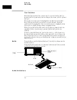


Probing
This chapter contains a description of the probing system for the logic
analyzer. It also contains the information you need for connecting the
probe system components to each other, to the logic analyzer, and to
the system under test.
Probing Options
You can connect the logic analyzer to your system under test in one of
the following ways:
•
Agilent Technologies 10320C User-Definable Interface (optional).
•
Microprocessor and bus specific interfaces (optional).
•
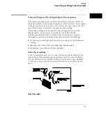
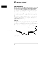
Standard general-purpose probing (provided).
•
Direct connection to a 20-pin, 3M-Series type header connector
using the optional termination adapter.
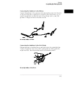
The 10320C User-Definable Interface
The optional 10320C User-Definable Interface module combined with
the optional Agilent Technologies 10269C General Purpose Probe
Interface allows you to connect the logic analyzer to the
microprocessor in your target system. The 10320C includes a
breadboard that you custom wire for your system.
Another option for use with the interface module is the Agilent
Technologies 10321A Microprocessor Interface Kit. This kit includes
sockets, bypass capacitors, and a fuse for power distribution. Also
included are wire-wrap headers to simplify wiring of your interface
when you need active devices to support the connection requirements
of your system.
See Also
Accessories for Agilent Logic Analyzers
for additional information
about the interface module and the microprocessor interface kits.
2–2
Содержание 1660A Series
Страница 5: ...vi...
Страница 14: ...1 Introduction...
Страница 24: ...2 Probing...
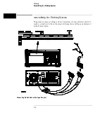
Страница 35: ...Probing Assembling the Probing System 2 12...
Страница 36: ...3 Using the Front Panel Interface...
Страница 65: ...3 30...
Страница 66: ...4 Using the Mouse and the Optional Keyboard...
Страница 74: ...5 Connecting a Printer...
Страница 91: ...5 18...
Страница 92: ...6 Disk Drive Operations...
Страница 118: ...7 The RS 232C GPIB and Centronix Interface...
Страница 121: ...RS 232 GPIB Menu Map Cont The RS 232C GPIB and Centronix Interface 7 4...
Страница 123: ...Printer Controller Menu Map Cont The RS 232C GPIB and Centronix Interface 7 6...
Страница 132: ...8 The System Utilities...
Страница 137: ...9 The Common Menu Fields...
Страница 150: ...9 14...
Страница 151: ...10 The Configuration Menu...
Страница 159: ...11 The Format Menu...
Страница 161: ...Format Menu Map The Format Menu 11 3...
Страница 194: ...11 36...
Страница 195: ...12 The Trigger Menu...
Страница 198: ...Trigger Menu Map The Trigger Menu 12 4...
Страница 199: ...Trigger Menu Map Continued The Trigger Menu 12 5...
Страница 235: ...13 The Listing Menu...
Страница 237: ...Listing Menu Map The Listing Menu 13 3...
Страница 260: ...13 26...
Страница 261: ...14 The Waveform Menu...
Страница 263: ...Waveform Menu Map The Waveform Menu 14 3...
Страница 264: ...Waveform Menu Map cont The Waveform Menu 14 4...
Страница 300: ...14 40...
Страница 301: ...15 The Mixed Display Menu...
Страница 306: ...15 6...
Страница 307: ...16 The Chart Menu...
Страница 310: ...Chart Menu Map The Chart Menu 16 4...
Страница 311: ...Chart Menu Map cont The Chart Menu 16 5...
Страница 336: ...16 30...
Страница 337: ...17 The Compare Menu...
Страница 340: ...Compare Menu Map The Compare Menu 17 4...
Страница 355: ...18 Error Messages...
Страница 363: ...19 Specifications and Characteristics...
Страница 377: ...20 Operator s Service...
Страница 386: ...Troubleshooting Flowchart 1 Operator s Service To use the flowcharts 20 10...
Страница 387: ...Troubleshooting Flowchart 2 Operator s Service To use the flowcharts 20 11...


