


13
ArtNo.302-0002 - 6BC annotated
ArtNo.302-0002 - 6BC annotated
ArtNo.302-0002 - 6BC annotated
ArtNo.302-0002 - 6BC annotated
ArtNo.302-0002 - 6BC annotated
ArtNo.302-0002 - 6BC annotated
ArtNo.302-0002 - 6BC annotated
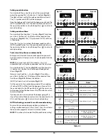
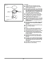
Setting a cook duration
Press and hold the [
] button and set the required ‘cook
period’ by pressing the [+] button (or [–] button) (
Fig. 4.6
).
The clock will now control the cook period of your oven(s).
The [
] symbol and [AUTO] will be displayed.
Once the ‘cook period’ is reached, the beeper sounds and the
[AUTO] symbol flashes. Turn the oven control knob to 0 and
then press any button to stop the beep. Press [
] to return to
manual cooking.
Setting a cook end time
Press and hold the ‘stop time’ [
] button (
Fig. 4.7
) and then
press the [+] button (or [–] button) until the required ‘stop
time’ shows (
Fig. 4.8
). The [
] symbol and [AUTO] will show
in the display.
Once the
‘stop time’
is reached, the beeper sounds and the
[AUTO] symbol flashes. Turn the oven control knob to 0 and
then press any button to stop the beep. Press [
] to return to
manual cooking.
To start and stop the ovens automatically
Before you set the clock for automatic operation you must
have two numbers clearly in mind – the ‘cook period’ and the
‘stop time’.
NOTE:
You cannot set a start time directly – this is set
automatically by setting the ‘cook period’ and the ‘stop time’.
Press and hold the [
] button (
Fig. 4.9
) and then press the
[+] button (or [–] button) until the required ‘cook period’
shows (
Fig. 4.10
).
Now press and hold the [
] button (
Fig. 4.11
) and then
press the [+] button (or [–] button) until the required ‘stop
time’ shows (
Fig. 4.12
). Release the buttons.
[AUTO] will now show in the display (
Fig. 4.13
).
Set the oven(s) to the required temperature. When cooking
is finished [AUTO] will flash and the beeper will sound. Turn
the oven knob(s) to the OFF position first, and then press any
button once to stop the beep; press the [
] button to return
to manual cooking.
If you are out, do not worry about the beeper going off, it
stops after a while. When you return, turn the oven knob(s) to
0 first, and then press [
] to return to manual cooking.
AUTO is showing, you want to reset to manual cooking
To return to manual cooking mode from an Automatic
setting, simultaneously press the [+] and [-] key, this will clear
the automatic program and return to manual mode.
NOTE
: This action will also clear the [Minute Minder] setting.
Fig. 4.7
Fig. 4.8
Fig. 4.9
Fig. 4.10
Fig. 4.11
Fig. 4.12
Fig. 4.13
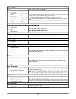
Symbol
Function
Notes
[
]
Sets the Minute Minder Used with the [+] and [-] buttons
[
]
Sets the duration / cook
period
Used with the [+] and [-] buttons
[
]
Sets the end / stop cook
time
Used with the [+] and [-] buttons
[
]
or
[
]
&
[
]
Allows the time of day to
be set when ‘AUTO’ is not
active
Used with the [+] and [-] buttons
[
]
Resets the cooking control
to manual
[
-
]
Decreases time interval
Holding this button down
allows a quick set
[
+
]
Increases time interval
Holding this button down
allows a quick set
[
+
]
&
[
-
]
Clears all ‘AUTO’ and
minute minder programs
Table 4.2