R01.43
22.10.2018
Page 89
5 First commissioning
Assembly of the system
The aflex is mounted. Information about it can be found in the chapter Installation in-
structions and the accompanying Quick Guide.
The control unit is installed and connected according to the circuit diagram. Refer also
to the chapter Installation instructions and the accompanying circuit diagram.
Connect to control unit
The configuration software "aflexConfigurator" must be installed. If the configuration
software and the control unit are located in the same network, the control unit is found
using the "Search" button. The Windows firewall can block this UDP broadcast de-
pending on the company setting. If this is the case, there are two options.
1. Establish a direct connection between the computer and control unit with an
Ethernet cable. Since the control unit is configured with the DHCP in the delivery
state, no IP adjustments have to be made.
2. Add the IP address from the delivered test report manually using the "add con-
trol unit" function
Detailed information can be found in the section Software description .
Configure ControlUnit
The IP address & device name of the control unit is adapted to the application.
Detailed information can be found in the section Software description .
Configure client nodes
The control modules are preconfigured in the delivery state. All channels of the T4X
drivers are in "Pulse Mode Continuous" and the "Channel Max Power" is set to the
aflex actuator. The channel names are defined accordingly. These settings should not
be changed during commissioning!
Detailed information can be found in the section Software description .
A new configuration is necessary only in the case of a driver exchange or an aflex
exchange. In these cases, following care must be taken:
- The maximum power of the actuators is adjusted in the resonance frequency
of the aflex so that no mechanical contact is created between the vibrating
plate and the frame. The noise level of the aflex increases significantly with a
slight mechanical contact, and the vibration plate can be heard. If the power of
the actuator is further increased, the vibration plate remains attached to the
frame and the vibrations are almost completely damped. In these cases, the
maximum intensity of the actuator must be reduced.
Содержание aflex 150 qc
Страница 36: ...Page 36 22 10 2019 R01 43 ...
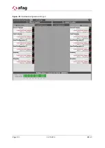
Страница 100: ...Page 100 22 10 2019 R01 43 Figure 79 Fieldbus Konfiguration IO Typ 3 ...


