Page 44
22.10.2019
R01.43
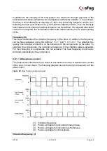
All actuators are controlled according to the oscillation frequency. The process is re-
peated periodically. The on and off times of the actuators are defined in percent [%].
For example, a start time of 50% corresponds to a half period
𝒇
𝟐
. A stop time of 100%
corresponds to the end of the period
𝑓
.
Diagram horizontal primary phase (2)
The horizontal primary phase pulls the vibrating plate into the desired direction of mo-
tion by controlling the corresponding horizontal actuator. Through the superimposition
of vertical and horizontal actuators, components can be conveyed in this way. Vertical
and horizontal actuators are offset in time (2) (4). If this is not the case, the components
are conveyed in the opposite direction.
Diagram horizontally inverted phase (3)
After the horizontal primary phase is turned off, the plate swings back to its rest posi-
tion. This movement is amplified by the horizontal inverted phase. The horizontal in-
verted phase controls the actuator opposite the horizontal primary phase. The horizon-
tal inverted phase is controlled as a short pulse at the end of the horizontal primary
phase (2) (3).
Diagram vertical phase (4)
The vertical actuators are steered timely to the horizontal actuators. The components
are excited by the vertical vibrations of the plate.
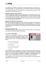
4.5.2 Aflex configurations
In order to enable different components or movement
sequences to be used on the aflex, so-called "configu-
rations" are used. Each configuration contains a param-
eter set of aflex control. The following parameters are
saved:
o
horizontal primary phase
o
horizontal inverted phase
o
vertical phase
o
horizontal maximum power
o
vertical maximum power
o
frequency
When loading a saved configuration, the current parameters are overwritten with the
loaded ones. There is no configuration monitoring, i.e. the parameters are overwritten
once, the current parameters are subsequently changed, no automatic correction is
carried out. The last loaded configuration is displayed in aflexConfigurator. The
fieldbus output "LoadConfigNumber" also shows the last loaded configuration.
The configurations are loaded or saved in the control interface. These functions are
described in more detail below.
Содержание aflex 150 qc
Страница 36: ...Page 36 22 10 2019 R01 43 ...
Страница 100: ...Page 100 22 10 2019 R01 43 Figure 79 Fieldbus Konfiguration IO Typ 3 ...

