P a g e
|
17
1
2
3
4
ON
D
I
P
SLAVE IN
SLAVE OUT
1 2 3
1 2 3
IN
+
2
4V
-
O
U
T
+
2
4V
-
IN
1
2
3
O
U
T
1
2
3
COI L
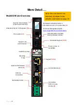
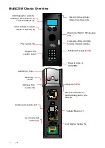
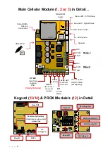
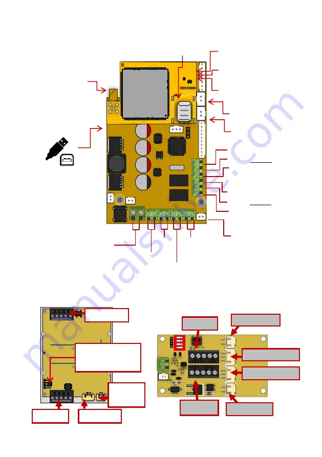
Main Cellular Module (
1, 2 or 3
) in Detail…
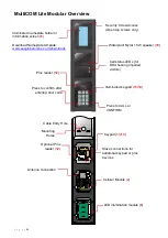
Keypad (
13
/
14
) & PROX Module’s (
12
) in Detail
R
V
T
R
V
T
RVT
RVT
RVT
RVT
Q UE
C TE
L
Q UE
C TE
L
SLAVE IN
SLAVE OUT
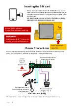
12-24V
OUT
1 2 3
12-24V
OUT
1 2 3
Relay 2
DETECT
Gate Position
Limit switch
(optional)
OPEN
Exit Button
PB
To Call
Button
12V = 12v DC
Output 100mA
(backlighting)
DC 24V
Input from
supplied
PSU
Relay 1
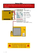
Green LED = CPU Status
Blue LED = Signal Status
Red LED = Power
NANO SIM
holder
Female SMA
Antenna
Connection
N/O
COM
N/C
N/O
COM
N/C
USB-B Port
Microphone
Speaker
Slave IN
DATA
DC
Voltage In
Slave OUT
DC Voltage Out
Slave IN
Connectio
ns
DATA Transfer OUT
DATA Transfer IN
IN
DC Voltage In
Slave OUT
Connection
s
12V DC OUT
Push Button
Illumination
Polarity Protected
Master only/Auxiliary
(Baud rate on older units)
Jumper Link
Содержание MultiCOM Cellular Series
Страница 3: ...P a g e 3 PHASE 1 Site Survey...
Страница 5: ...P a g e 5 PHASE 2 Product Overview...
Страница 6: ...P a g e 6 Overview of Intercoms Imperial Design Antenna Separate...
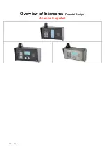
Страница 7: ...P a g e 7 Overview of Intercoms Pedestal Design Antenna Integrated...
Страница 8: ...P a g e 8 Overview of Intercoms Flush Design Antenna Separate...
Страница 9: ...P a g e 9 Overview of Intercoms Modular Pre Set Design Antenna Separate...
Страница 22: ...P a g e 22 PHASE 3a Setup Programming To be done before installing the intercom...
Страница 29: ...P a g e 29 PHASE 3b PC Programming Windows Compatible Only...
Страница 36: ...P a g e 36 PHASE 4 Using the Intercom Only to be done after the unit is successfully programmed...
Страница 40: ...P a g e 40 PHASE 5 Installation...
Страница 46: ...P a g e 46 PHASE 7 Aftercare...
Страница 54: ...P a g e 54...
Страница 55: ...P a g e 55...


