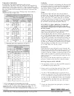
Temperature Limitations
For maximum valve ambient temperatures, refer to chart.
The temperature limitations listed, only indicate maximum application
temperatures for field wiring rated at 90'C. Check catalog number prefix
and watt rating on nameplate to determine maximum ambient temperature.
See valve installation and maintenance instructions for maximum fluid
temperature.
NOTE:
For steam service, refer to Wiring section, Junction Box for
temperature rating of supply wires.
§ Minimum ambient temperature 40’F (40°C).
¹ = EF, EV data applies to Explosionproof coils only.
² = Some DC solenoid valves can be operated at maximum ambient
temperature of 55°C/ 131°F with reduced pressure ratings. See valve
I&M for maximum operating pressure differential ratings.
³ = Steam Service Valves have a maximum ambient temperature of 55°
C/ 131°F.
Positioning
This solenoid is designed to perform properly when mounted
in any position. However, for optimum life and perfonnance,
the solenoid should be mounted vertically and upright to
reduce the possibility of foreign matter accumulating in the
solenoid base sub-assembly area.
Wiring
Wiring must comply with local codes and the National
Electrical Code. All solenoids supplied with lead wires are
provided with a grounding wire which is green or green with
yellow stripes and a 1/2" conduit connection. To facilitate
wiring) the solenoid may be rotated 360°. For the watertight
and explosionproof solenoid, electrical fittings must be ap
-
proved for use in the approved hazardous locations.
ii.CAUTION: Cryogenic Applications - Solenoid lead
wire insulation should not be subjected to cryogenic
temperatures. Adequate lead wire protection and routing
must be provided.
Additional Wiring Instructions For Optional Features:
Open-Frame solenoid with 1/4" spade terminals,
For solenoids supplied with screw terminal connections use
#12- 18 AWG stranded copper wire rated at 90°C or greater.
Torque tenninal block screws to 10±2 in-lbs [1,0±1,2 Nm].
A tapped hole is provided in the solenoid for grounding, use
a #10-32 machine screw. Torque grounding screw to 15·20
in-lbs [1,7· 2,3 Nm]. On solenoids with screw tenninals, the
socket head screw holding the tenninal block to the solenoid
is the grounding screw. Torque the screw to 15-20 in-lbs
[1,7-2,3 Nm] with a 5/32" hex key wrench.
Junction Box
The junction box is used with spade or screw terminal sole-
noids only and is provided with a grounding screw and a 1/2"
conduit connection. Connect #12-18 AWG standard copper
wire only to the screw terminals. Within the junction box use
field wire that is rated 90°C or greater for connections. For
steam service use 105°C rated wire up to 50 psi or use 125°C
rated wire above
50 psi. After electrical hookup, replace cover gasket, cover,
and screws. Tighten screws evenly in a crisscross manner.
DIN Plug Connector Kit No. K236034
The open-frame solenoid is provided with DIN terminals to
accommodate the plug connector kit.
Remove center screw from plug connector. Using a small
screwdriver) pry tenninal block from connector cover.
Use #12-18’AWG stranded copper wire rated at 90°C or
greater for connections. Stri}) wire leads back approximate-
ly 1/4” for installation in socket terminals. The use of wire-
end sleeves is also recommended for these socket terminals.
Maximum length of wire-end sleeves to be approximately
1/4”. Tinning of the ends of the lead wires is not recom-
mended.
Tbread wire through gland nut, gland gasket, washer and
connection cover.
4.
3.
1.
2.
l&M V 6584 R16 sec1
www.ascovalve.com
©ASCO Valve, Inc. 50 Hanover Road, Florham Park, New Jersey 07932
1
1

