


33
PD201808 AEG GRID-TIED THREE-PHASE SOLAR INVERTER (12-30 kW) V.2-18 EN
33
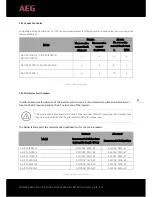
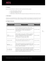
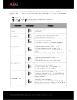
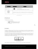
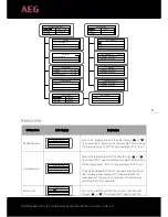
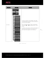
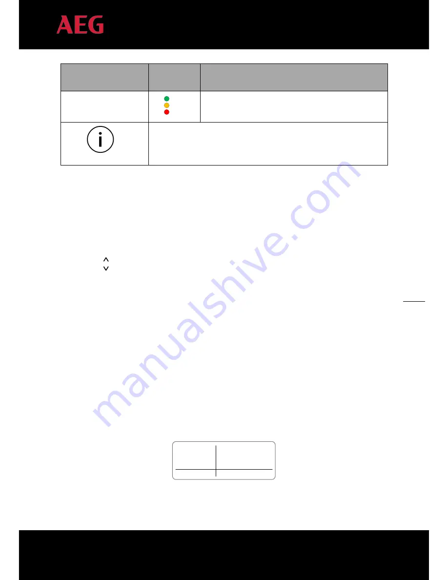
Inverter state
LED indicators
Description
Manual turn off
Run
Warn
Fault
All indicators are on:
Stop after the communication or panel command.
Please refer to chapter 5 and 7 for detailed fault information and troubleshooting.
Table 15A: Inverter states
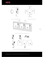
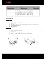
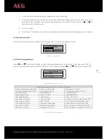
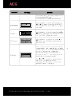
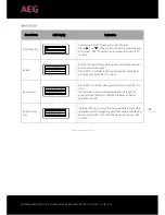
5.2 Operation panel
There are 4 buttons on the panel:
1.
“ESC”, exit and return ;
2.
“ ”, back to the front page and data increasing;
3.
“ ”
,
to the next page and data decreasing;
4.
“ENT”, enter.
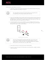
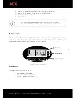
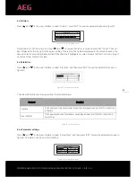
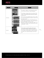
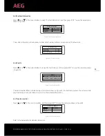
5.3 LCD display
All information is displayed on the LCD screen. If there is no button operation in 15 seconds, the LCD screen will dim out
to save power. It can be activated again by pressing any button. When the LCD screen is active, press “ENT” to enter the
main interface. All parameters can be viewed and set on the interface.
The LCD screen features a main interface and menu interfaces, The main interface is the default one when the inverter
is turned on; the menu interfaces are used to set parameters and for other manual operation, such as viewing the moni-
toring parameters, history record, system information, statistics fault information, language / time settings, communica-
tion address, password and factory default settings.
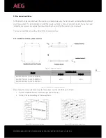
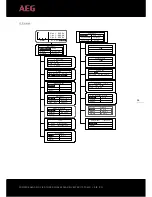
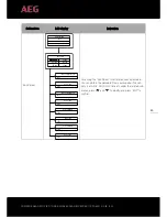
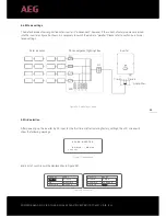
Text Parameter
Display Area
Fault Code Menu
Status Area
Curve Graphic
Display Area
Figure 16B: Main interface
Figure 16B above shows the main interface of the LCD screen. The LCD screen displays the following items:


