


87
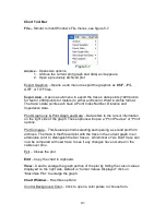
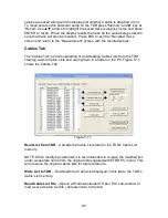
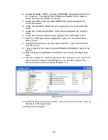
Figure 5-4
NOTE: If you plan to connect multiple TDRSs (one at a time at different times) to
the same PC refer to “Preventing Auto Increment of the Serial Port When Using
the AEA E2020 TDR USB Serial Interface” later in this section.
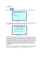
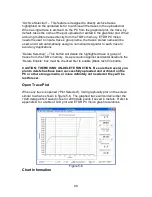
If the only work to be done with the TDR involves uploading current traces or
archived traces, continue working with the “Get Trace” tab shown in Figure 5-2.
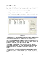
For work with traces stored in the TDR’S’s memory click on the “Saved Traces”
tab and skip to next sub-section “Saved Traces Tab” in this section of the
manual.
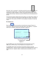
NOTE: When uploading the current trace, the TDR does not know where the
cable ends. It will only upload the presentation on the TDR’s LCD plot display.
This provides the option to upload only a segment of interest on the cable or the
entire length if the range is set beyond the cable’s end.
“Plot Current Trace” – Press to upload the current trace displayed in the TDR’S’s
Measurement Screen.
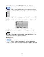
“Plot Archived Trace” – This button will open a folder on the PC to select a
previously stored trace or move to a folder or PC connected storage media for
selecting a previously stored trace (TDR connection is optional with this action).
NOTE: Default Locations for data files supplied with ETDR PC Vision (or …
where did Windows put my files???)
Different versions of MS Windows
®
use different locations to install the Cable
Tables and the demo archived trace files supplied with this software. Refer to
this subject (as underlined) at the end of this section for the paths used by
Windows XP
®
, Vista
®
, and Win7
®
.
Содержание E20/20
Страница 1: ...Step Time Domain Reflectometer E20 20 Step TDRs and Avionics TDR all models ...
Страница 40: ...33 Figure 3 8 Figure 3 9 Figure 3 10 ...
Страница 79: ...72 ...
Страница 109: ...102 This page intentionally left blank ...


