


60
You can shift control between the two cursors as required. The LEDs and LCD
legends operate as usual to indicate which cursors are in use and which one is
active.
To restore Zoom operation press the
key once and use the
◄►
keys to
control the zoom range. (Alternate method, if only one cursor LED is lit, press the
lit cursor key once to release cursor control. Now the
◄►
keys control the zoom
range).
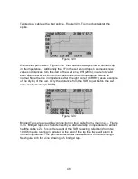
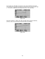
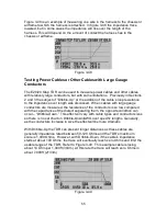
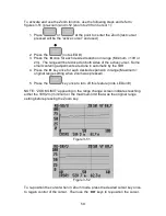
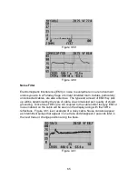
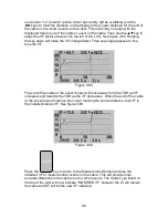
In figure 3-52 note that Cursor 1 has been repositioned closer to the fault than it
could be in figure 3-51. New distance to fault is now 52 ft 7 inches (16m).
Start Distance
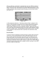
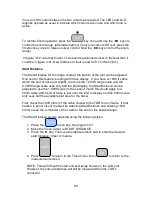
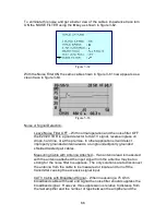
The Start Distance for the range scale at the bottom of the plot can be adjusted.
One use for this feature is aiding with trace display. If you have a 1,000 ft cable
which the end of trace just slightly over runs the 1,000 ft range scale and the
2,000ft range scale uses only half the plot display, the Start Distance can be
adjusted to use the 1,000ft scale (In the case of metric this would apply to a
200m cable which end of trace is just over the limit to display and the 500m scale
only uses half the available plot area for the trace).
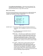
First, check the 100ft (30m) of the cable closest to the TDR for any faults. If that
section is good, off-set the start by selecting Start Distance and entering 100ft
(30m) to see the remainder of the cable to the end on the desired range.
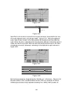
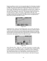
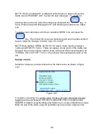
The Start Distance can be adjusted using the following steps:
1. Press the
menu key. See figure 3-53
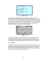
2. Move the menu cursor to START DISTANCE
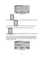
3. Press the
►
key. Then use the alpha-numeric pad to enter the desired
start distance in feet or meters.
4. Press
to return to the Trace menu, then
to return to the
measurement screen.
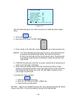
NOTE: This will off-set the start and end range shown on the LCD plot.
However, the cursor distances will still be measured from the TDR’s
connector.
Содержание E20/20
Страница 1: ...Step Time Domain Reflectometer E20 20 Step TDRs and Avionics TDR all models ...
Страница 40: ...33 Figure 3 8 Figure 3 9 Figure 3 10 ...
Страница 79: ...72 ...
Страница 109: ...102 This page intentionally left blank ...


