TREK
‐
510
User
manual
16
2.1
A
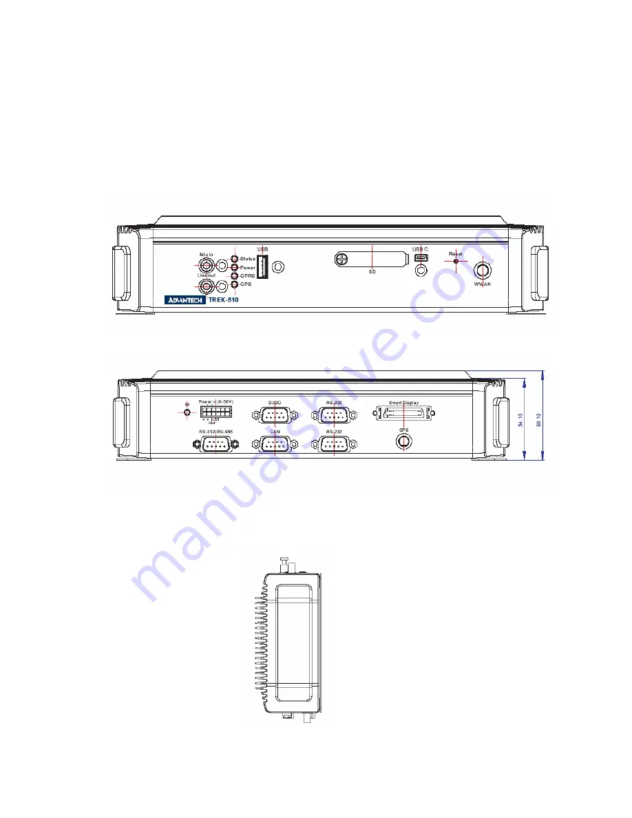
Quick
Tour
of
the
TREK
‐
510
Computing
box.
Before
starting
to
set
up
the
In
‐
Vehicle
Computing
Box,
take
a
moment
to
become
familiar
with
the
locations
and
purposes
of
the
controls,
drives,
connectors
and
ports,
which
are
illustrated
in
the
figures
below.
When
the
Computer
box
is
placed
inside
truck
glove
cabinet
or
under
the
passenger’s
seat
next
to
the
driver,
its
front
appears
as
shown
in
Figure
2.1.
Figure
2.1.
Front
view
of
TREK
‐
510
Figure
2.2.
Rear
view
of
TREK
‐
510
Unit:
mm
Содержание TREK-510
Страница 1: ...TREK 510 User manual 1 User Manual TREK 510 In VehicleComputingBox SmartDisplay User manual...
Страница 10: ...TREK 510 User manual 10...
Страница 17: ...TREK 510 User manual 14 1 3 Dimensions Figure 1 1 TREK 510 dimensions...
Страница 46: ...TREK 510 User manual 46 Figure 6 14 Step 4 Choose setup type Figure 6 15 Figure 6 16...
Страница 47: ...TREK 510 User manual 47 Step 5 Tap Install button to install SDK Figure 6 17 Install SDK...
Страница 50: ...TREK 510 User manual 50 4 Software Hardware reset 5 Get bootloader version 6 Digital I O access...
Страница 60: ...TREK 510 User manual 60 Appendix A C TREK 303 This This appendix explains the TREK 303 detailed information...
Страница 65: ...TREK 510 User manual 65 Appendix B C Windows Embedded CE 5 0 Component List This...
Страница 87: ...TREK 510 User manual 87...


