36
Apply Delay to Outputs for Selected Zones
The activation of sounder circuits and aux outputs can be delayed in response to selected zones. The actual
delay time is set up in the panel wide programming options, 2-1-2-3.
The setting of delays here applies to all sounder circuits, all aux outputs or all sounder circuits and all aux
outputs.
Individual outputs can be programmed to be active during a delay in the output functional options.
To apply the delays for selected zones, enter the above code
and press ENTER.
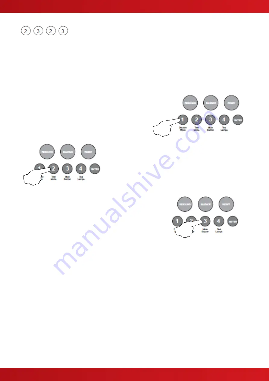
The zone 1 fire LED will illuminate. This indicates that delays
are being applied for zone 1. Use button 1 to move the LED to
the required zone for programming.
With the required zone LED lit, press the ENTER button to enter
‘edit mode’. The fire LED will now pulse. Now use button 2 to
turn on delays, this is indicated by the zone, amber, fault /
disabled / test LED, ON.
Pressing button 2 again will toggle the delays ON & OFF,
indicated by the zone, amber, fault / disabled / test LED.
With the amber LED, ON, use button 3 to select which outputs are
to be delayed. The choice toggles between, all sounder circuits, all
aux outputs or all sounder circuits and all aux outputs.
The selection is indicated by the Sounder Status LED and the Aux
Output Status LED.
When finished programming for the zone, press the ENTER button again to return to the zone selection,
indicated by a steady fire LED.
If a delay has been applied to a zone, the Delay Status LED will be lit permanently, to indicate that a
programmed delay exists. When a fire condition is active in a zone with a delay, the Delay Status LED will
pulse, when the delay time has expired the LED will extinguish.
To override a delay a 220Ω ‘Evacuate’ call point can used or a different zone can be activated that has no
delays programmed.
When the Delay Status LED is active, the delay can be temporarily disabled using the panel’s disablements
feature. If the delay has been disabled the Delay Status LED will be extinguished.
When finished, press and hold Button 1 for 3 seconds to save setting and exit programming mode
Enter the next programming code or disable the controls and return DIL switch 3 t
o ‘OFF’.
www.acornfiresecurity.com
www.acornfiresecurity.com
Содержание Quick Zone XL
Страница 5: ...5 1 2 CABINET DETAILS www acornfiresecurity com www acornfiresecurity com...
Страница 8: ...8 1 4 MAIN PCB TERMINALS www acornfiresecurity com www acornfiresecurity com...
Страница 14: ...14 2 2 GENERAL CONVENTIONAL SYSTEM SCHEMATIC www acornfiresecurity com www acornfiresecurity com...
Страница 15: ...15 2 3 GENERAL TWIN WIRE SYSTEM SCHEMATIC www acornfiresecurity com www acornfiresecurity com...
Страница 66: ...66 This page is intentionally left blank www acornfiresecurity com www acornfiresecurity com...
Страница 67: ...USER NOTES www acornfiresecurity com www acornfiresecurity com...
Страница 68: ...www acornfiresecurity com www acornfiresecurity com...


