


Advanced Instruments Inc.
Mounting the Analyzer and Sensor
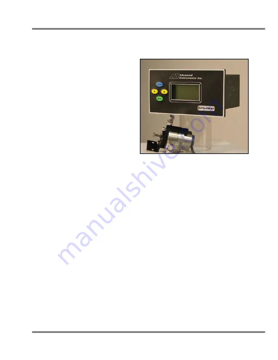
The GPR-IN190 consists of a six (6) foot insulated
cable which connects the sensor to the rear of the
electronics module, a long life maintenance free
oxygen sensor and a stainless steel sensor
housing equipped with 1/8” diameter stainless
steel compression fittings.
The compact design also lends itself to optional
mounting configuration such as a standard 19”
rack or wall mount enclosures, both of which can
be equipped with optional sample system
components. Contact the factory for additional
information.
Procedure:
1.
The GPR-IN190 front panel measures 7”W x
4”H x 4.5”D. This compact configuration is
designed for panel mounting directly to any
flat vertical surface, wall or bulkhead plate
with the appropriate 6”W x 3”H cut out and
four ¼” diameter holes for insertion of the
mounting studs located on the back side of
the front panel.
2.
When mounting the analyzer position it
approximately 5 feet off the floor for viewing
purposes and allow sufficient room for access
to the terminal connections at the rear of the enclosure.
3.
Position the sensor housing along any flat surface. The bracket attached to the sensor housing is fabricated with
two 6/32 mounting holes. The oxygen sensor is not position sensitive but it is recommended to orient the sensor
housing with the upper section identified by the interconnection cable facing the ceiling.
4.
If not already connected, connect the four wires of the sensor housing cable, following the color coding noted at
the terminal block, at the rear of the analyzer.
5.
Mount the sensor housing as suggested above.
6.
Do not install the sensor at this time, see below.
Gas
Connections
The GPR-IN190 with its standard flow through configuration is designed for positive pressure samples and requires
connections for incoming sample and outgoing vent lines. The user is responsible for calibration gases and the
required components, see below. Flow rates of 1-5 SCFH cause no appreciable change in the oxygen reading.
However, flow rates above 5 SCFH generate backpressure and erroneous oxygen readings because the diameter of
the integral tubing cannot evacuate the sample gas at the higher flow rate. A flow indicator with an integral metering
valve upstream of the sensor is recommended as a means of controlling the flow rate of the sample gas. A flow rate
of 2 SCFH or 1 liter per minute is recommended for optimum performance.
14


