26
•
Getting Started
3.
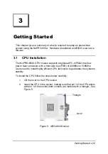
Press the lever down until you hear it “click” into the locked position.
4.
Apply the proper amount of thermal compound to the CPU die and
place the heatsink and fan on top of the CPU.
5.
Connect the three wires of the CPU fan to the respective CPU fan
connector.
Note:
Ensure that the CPU heat sink and the CPU top surface are in tight
contact to avoid CPU overheating problem that would cause your
system to hang or crash. The CPU heat sink and fan should be
installed tightly together. Please contact ADLINK dealers for suitable
heat sink and fan assemblies
3.2 Memory
Installation
This section details the procedure for installing system memory on the
NuPRO-900A. Correct memory configuration is critical for proper system
operation.
3.2.1
Memory Configuration Options
The NuPRO-900 has flexible memory configuration options. These include
support for 64MB, 128MB, 256MB, 512MB, 1GB & 2GB Modules. Note that
the modules must all be the same type and density and must be installed in
pairs and if only one pair of DIMM modules are used, populate DM1 and DM2
first.
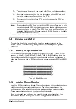
Figure 6: DIMM Sockets
3.2.2
Installing Memory Modules
Installing DIMM modules is simple. The modules insert in the sockets and are
held in place by the socket retaining arms. The edge connectors on the
modules are of different widths and there are key notches in each module.
These ensure that you cannot insert a module incorrectly.
Before you install any modules, you should choose a configuration. You
should then prepare the required number and type of DDR modules.
Содержание NuPRO-900A
Страница 2: ...NuPRO 900A Full Size ePCI X System Host Board with Dual Xeon CPU User s Guide Recycled Paper ...
Страница 3: ......
Страница 14: ...Introduction 5 Main Board Drawing Figure 2 Main Board Drawing ...
Страница 21: ......
Страница 32: ...Jumpers and Connectors 23 2 3 Clear CMOS Use one conductor to touch JP2 pin1 2 to clear CMOS JP2 3 2 1 ...
Страница 33: ......
Страница 39: ......
Страница 43: ......


