


Jumpers and Connectors
•
15
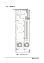
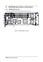
2.1.2 Front
View
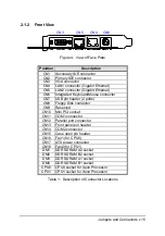
Figure 4: View of Face Plate
Position
Description
CN1
Secondary IDE connector
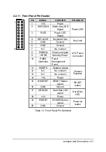
CN2
Primary IDE connector
CN3 VGA
connector
CN4
LAN1 connector (Gigabit Ethernet)
CN5
LAN2 connector (Gigabit Ethernet)
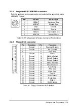
CN6 Integrated
Keyboard/Mouse connector
CN7
USB pin header (2 ports)
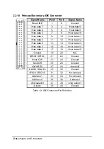
CN8
Floppy Disk connector
CN9 Reserved
CN10
Mini PCI socket
CN11 COM1
connector
CN12
Parallel port connector
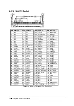
CN13
Front panel pin header
CN14 COM2
connector
CN15
Case open pin header
CN16
Fan1 (for CPU0)
CN17
ATX power connector
CN18
Fan2 (for CPU1)
DM1
DDR SDRAM A2 socket
DM2
DDR SDRAM B2 socket
DM3
DDR SDRAM A1 socket
DM4
DDR SDRAM B1 socket
CPU0 CPU0 socket for Xeon Processor
CPU1 CPU1 socket for Xeon Processor
Table 1: Description of Connector Locations
CN3
CN5
CN4
CN6
Содержание NuPRO-900A
Страница 2: ...NuPRO 900A Full Size ePCI X System Host Board with Dual Xeon CPU User s Guide Recycled Paper ...
Страница 3: ......
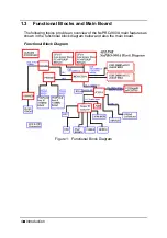
Страница 14: ...Introduction 5 Main Board Drawing Figure 2 Main Board Drawing ...
Страница 21: ......
Страница 32: ...Jumpers and Connectors 23 2 3 Clear CMOS Use one conductor to touch JP2 pin1 2 to clear CMOS JP2 3 2 1 ...
Страница 33: ......
Страница 39: ......
Страница 43: ......