When the Side A interface is shown, the Side A table is used to determine if packets received on
the Side A should be forwarded across and transmitted out the Side B . Likewise when the Side B
interface is shown, the Side B Table is used to determine if packets received on Side B should be
forwarded across and transmitted out Side A.
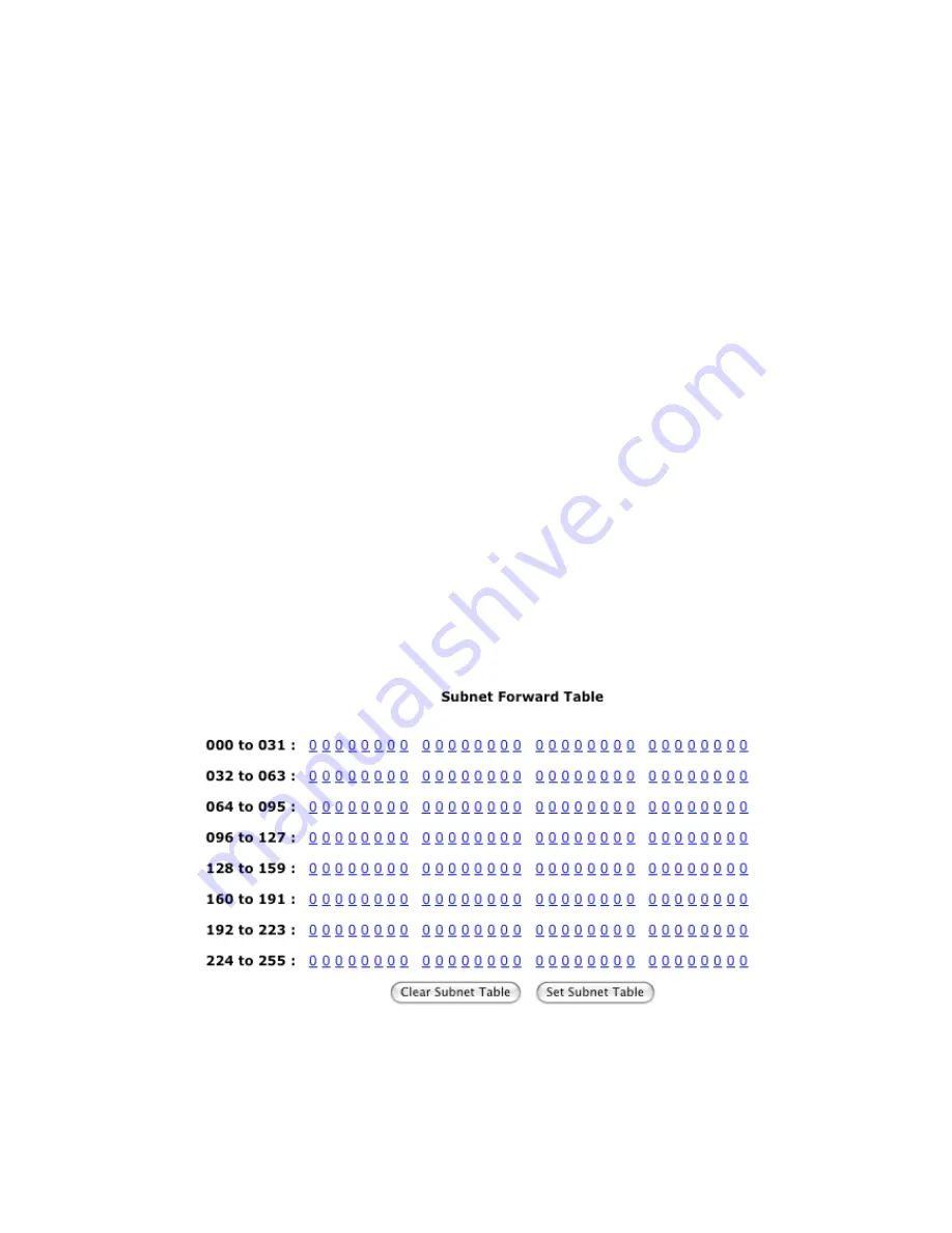
For each table the bits are displayed from le to right in increasing order of bit position. Bit
position one refers to subnet number one and so forth. Clicking on a bit will toggle the bit value
and store the new value in memory. A value of one in a bit position means forward, to the other
side of the router, packets addressed to the corresponding subnet or group. A value of zero in a bit
position means do not forward, to the other side of the router, packets addressed to the
corresponding subnet or group.
For example, a 1 in the subnet table on Side A means forward to side B any packets received on
Side A that are addressed to the corresponding subnet. A 0 in the subnet table on Side A means
do not forward any packets to side B that are addressed to the corresponding subnet. Likewise for
the group table.
Clear Subnet Table
: is button clears all the subnet bits by assigning each a value of zero and
stores the new values in memory.
Set Subnet Table
: is button sets all the subnet bits by assigning each a value of one and stores
the new values in memory.
Clear Group Table
: is button clears all the group bits by assigning each a value of zero and
stores the new values in memory.
Set Group Table
: is button sets all the group bits by assigning each a value of one and stores the
new values in memory.
Fig.2.18: Subnet Forwarding Table
-41-
Содержание GRouter4
Страница 1: ...GRouter4 Single Port 709 1 852 LON IP Router User Guide 4 12 2011 03 19 Document Revision 4 14 1...
Страница 25: ...Fig 2 8 Status Page 25...
Страница 26: ...Fig 2 9 Status Page with Bridge and Twin Mode Enabled 26...
Страница 42: ...Fig 2 19 Group Forwarding Table 42...
Страница 57: ...Fig 3 4 Side A Channel List Page in Manual Mode 57...
Страница 72: ...Fig 4 2 Initial LonMaker Drawing Fig 4 3 Router Channel Setup 72...
Страница 77: ...Fig 4 8 LonMaker New Device Channel Dialog Fig 4 9 LonMaker Drawing With Commissioned Monitoring Device 77...
Страница 78: ...Fig 4 10 New Virtual Functional Device Dialog Fig 4 11 Functional Blocks NV Shapes Dialog 78...