appropriate page. e button corresponding to the page that is currently displayed will be
highlighted in pink. Each of the pages in the web based Configuration Tool will be explained in
the following sections.
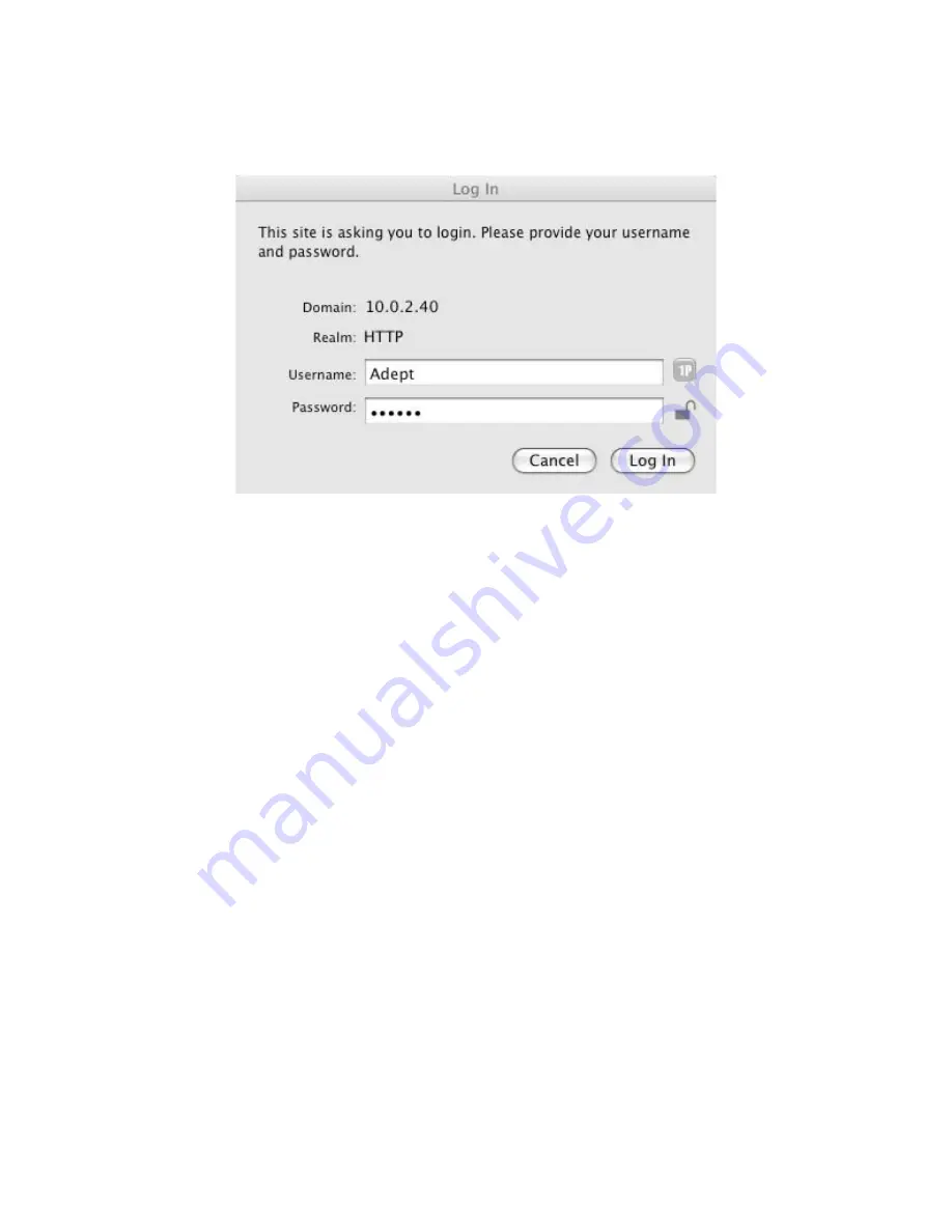
Fig.2.7: User Name and Password Authentication
Once communications have been established, new IP or WiFi parameters may be entered. e
procedure is as follows:
• Set up IP and/or WiFi interface between host computer and GRouter device using default
network settings
• Reconfigure the GRouter device to use new network settings
• Reconfigure the IP and or WiFi network to use new settings
• Reboot GRouter device and reestablish communications using new settings
• If communications with new settings cannot be established because of lost or incorrect
settings then revert GRouter device to factory defaults and start over.
2.3. Restoring Factory Defaults
e web Tool allows customization of the IP address, net mask, WiFi SSID and security settings,
HTTP port, web user name, and password. Should any of these settings be forgotten or setup
incorrectly, communication with the GRouter device may not be possible. In this event, the IP
settings on the GRouter device can be restored to factory defaults so that a known set of IP, WiFi,
and web parameters is in effect.
2.3.0.1. Basic Procedure
e basic procedure is to first reboot the device and then while its booting up press and hold one
of the service buttons.
To reboot the device, either press and release the Reset button or power cycle the GRouter device.
If powering down or resetting the device aer making any configuration changes, please use the
Prepare to Power Down
button on the Router Setup page to ensure that a flash write operation
-22-
Содержание GRouter4
Страница 1: ...GRouter4 Single Port 709 1 852 LON IP Router User Guide 4 12 2011 03 19 Document Revision 4 14 1...
Страница 25: ...Fig 2 8 Status Page 25...
Страница 26: ...Fig 2 9 Status Page with Bridge and Twin Mode Enabled 26...
Страница 42: ...Fig 2 19 Group Forwarding Table 42...
Страница 57: ...Fig 3 4 Side A Channel List Page in Manual Mode 57...
Страница 72: ...Fig 4 2 Initial LonMaker Drawing Fig 4 3 Router Channel Setup 72...
Страница 77: ...Fig 4 8 LonMaker New Device Channel Dialog Fig 4 9 LonMaker Drawing With Commissioned Monitoring Device 77...
Страница 78: ...Fig 4 10 New Virtual Functional Device Dialog Fig 4 11 Functional Blocks NV Shapes Dialog 78...


