


2. Web Configuration
e Web-based GRouter device interface allows the user to access and change configuration data
on the GRouter device by using any http Web browser attached to the network. is allows users
to make changes to the GRouter device remotely. is chapter familiarizes the user with the
various pages of the Web-based Interface and describes the steps necessary to changing
configuration data.
2.1. Default IP Configuration
e GRouter device is configured through a web browser such as FireFox, Internet Explorer,
Safari, or others. In order to connect to the GRouter device from a web browser, the GRouter
device and the computer running the web browser must be connected to the same IP network.
e factory default IP host address of the GRouter device is 10.0.2.40 with subnet mask of
255.255.255.0. e router's web server is serving http on port 80. e computer running the web
browser must be able to access the GRouter device's subnet.
Default Internet Configuration
IP Host Address 10.0.2.40
IP Subnet Mask 255.255.255.0
Web HTTP Port 80
2
.
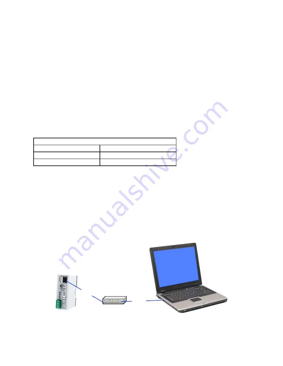
1.1. Ethernet
For Ethernet equipped GRouter devices, first configure the host computer to add an IP interface
on subnet 10.0.2.0/255. Connect one end of a Cat5 Ethernet cable to the RJ-45 on the GRouter
device and the other end to an Ethernet hub or switch or directly to a computer with a crossover
cable or straight through if the computer’s Ethernet port supports auto crossover (Auto MDIX).
e GRouter Ethernet port is MDI only. In cases where the LAN does not support the default
subnet, a direct connection between the GRouter device and the web browser host computer will
be needed.
Network Hub or Switch
Cat5
Cat5
Fig.2.1: Ethernet setup with hub or switch
-17-
Содержание GRouter4
Страница 1: ...GRouter4 Single Port 709 1 852 LON IP Router User Guide 4 12 2011 03 19 Document Revision 4 14 1...
Страница 25: ...Fig 2 8 Status Page 25...
Страница 26: ...Fig 2 9 Status Page with Bridge and Twin Mode Enabled 26...
Страница 42: ...Fig 2 19 Group Forwarding Table 42...
Страница 57: ...Fig 3 4 Side A Channel List Page in Manual Mode 57...
Страница 72: ...Fig 4 2 Initial LonMaker Drawing Fig 4 3 Router Channel Setup 72...
Страница 77: ...Fig 4 8 LonMaker New Device Channel Dialog Fig 4 9 LonMaker Drawing With Commissioned Monitoring Device 77...
Страница 78: ...Fig 4 10 New Virtual Functional Device Dialog Fig 4 11 Functional Blocks NV Shapes Dialog 78...


