


g
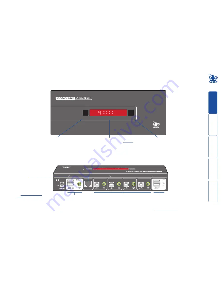
CCS4-USB features - top and rear
The CCS4-USB unit is housed within durable, metallic enclosure with all connectors situated at
the rear panel. The smart top panel features the control buttons and the operation indicators.
COMPUTER
K/M SPK USB1 USB2
MODE
www.adder.com
Indicators
The upper four indicators scroll across in sequence when the
Free-Flow
utility is engaged.
The lower four indicators (
K/M, SPK, USB, USB
) show which peripherals are switched
to the current computer channel OR (as you begin pressing the MODE button) the
peripherals that will be switched during the next press(es) of the COMPUTER button.
The seven segment numeric display indicates the computer channel that is currently active.
COMPUTER button
Press to change to the
next computer channel.
MODE button
Press to determine which peripherals
should be switched to another
computer channel (will occur when the
COMPUTER button is pressed.
4
3
2
1
5V
2.5A
I N D O O R
U S E
O N LY
OPTIONS
Options port
This 10p10c port can separately
support the following functions:
• Remote control - allows a
standard Adder RC4 four
button remote control unit to
be used to switch channels
(see
Optional.RC4.remote.
control
for details).
• Upgrades - used to update
the internal firmware when
necessary by connecting to a
computer.
User console
Connect a USB
keyboard and mouse
plus optional speakers
to these connectors.
Computer channels
Each computer connects to one
of these four channels via a USB
B-type connector and an audio
3.5mm jack input.
Power input
The power supply
connects here.
User console
Connect up to two USB
devices to these connectors.
These ports are switched in
an enumerated manner (see
What.is.True.Emulation?
)


