ADDER CCS4-USB Скачать руководство пользователя страница 14





















g











Free-Flow configuration

Installing the Free-Flow configuration application

The Free-Flow configuration application is supplied on the enclosed CD-ROM 
and is also available for download from the Adder website (

www.adder.com

).

1  Install the application onto any computer (not necessarily one of the four 

computers linked to the CCS4-USB unit) that has a vacant serial port. Run 
the installation application and follow the on-screen instructions.

2  Use the supplied Flash Upgrade Adaptor and a patch cable (VSC23 or any CAT5 

patch cable) to link the computer serial port to the CCS4-USB 

OPTIONS

 port.

3  Start the configuration application. 

Configuring the Free-Flow system

Use the Free-Flow configuration application to declare the display screens and 
their positions relative to each other. Then download the configuration to the 
CCS4-USB unit.

1  On the icon bar, click the red, green, blue and yellow screen icons (or use the 

Screens

 menu) to add the required number of display screens to the map area. 

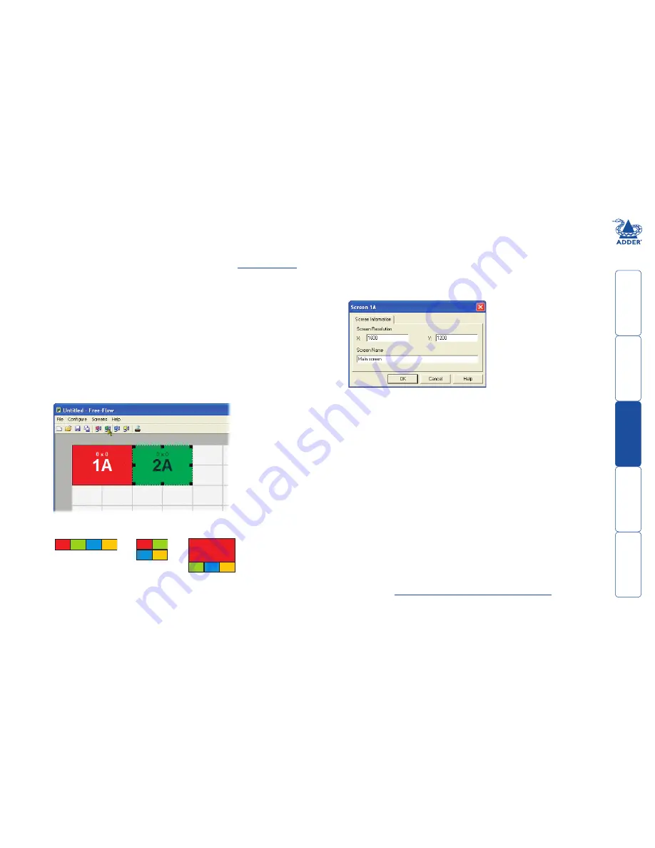
2  Arrange the coloured rectangular screen representations to mimic the 

physical layout of the actual displays, for example: 

3  Double-click on each screen representation to set the screen resolution and, 

optionally, to add a screen name. The screen resolutions are not critical but 
they enable the CCS4-USB unit to accurately map the movement of the 
mouse onto corresponding movements of the pointer across the screens. 
The screen names, if used, are not downloaded to the CCS4-USB unit.

1A

2A

3A

4A

1A

2A

3A

4A

1A

2A

3A

4A

  The important thing is to define where each screen edge abuts to the next so 

that the CCS-USB unit can determine the correct moments to switch channels. 

  Use the small black squares around the perimeter of each highlighted screen 

representation to change their size or stretch them.


Note: The numbering of the screen representations relate directly to the four 
channels on the CCS4-USB unit.

4  When the screen map is complete and accurately matches the true layout 

of the display screens, click 

File

 and choose the 

Save

 option to store a copy 

of the layout. The layout will be stored as a ‘Free-Flow Config file’ with the 
extension: 

.ffc

5  Ensure that the optional upgrade cable is correctly installed - see ‘Installing 

the Free-Flow configuration application’ left.

  Click the 

Configure

 menu and choose the 

Connection...

 option to ensure 

that the correct computer serial port is selected and that the Baud Rate 
matches that of the CCS4-USB unit (1200 is the default speed). 

6  To send the configuration, click the 

Send Layout to Switch

 option. 

•  If the download is successful, the upper four indicators on the CCS4-

USB unit will begin to scroll across (they will continue to do this while 
Free-Flow mode is enabled).

•  If the download is unsuccessful, a message dialog will explain that 

it is ‘Unable to communicate with the device’. Check the upgrade 
cable, check that the correct serial port is selected and check that the 
connection speed shown within the utility matches the speed used on 
the CCS4-USB unit.    

See next page for 

Optional.Free-Flow.operations.and.settings

Содержание CCS4-USB

Страница 1: ...CCS4 USB Four port keyboard and mouse switch Now with Free Flow switching technology...

Страница 2: ...switching 12 Miscellaneous functions 12 OPTIONS port speed 12 Free Flow configuration 13 Installing the Free Flow configuration application 13 Configuring the Free Flow system 13 Optional Free Flow o...

Страница 3: ...nity X50 and X USB to extend the distance between the user and the computers under control Switching between the systems connected to the CCS4 USB can be achieved in five different ways The innovative...

Страница 4: ...se moment to switch from one screen system to the next The beauty of Free Flow is its simplicity of configuration and operation Once the initial configuration has taken place all monitoring and switch...

Страница 5: ...of the necessary signals states and processes Therefore manufacturers have previously relied upon a fixed keyboard and mouse profile that is declared to each computer regardless of the actual connect...

Страница 6: ...ange to the next computer channel MODE button Press to determine which peripherals should be switched to another computer channel will occur when the COMPUTER button is pressed 4 3 2 1 5V 2 5A I N D O...

Страница 7: ...patch lead Part number VSC23 Power adapter 12 5W and country specific power lead Audio cable 2m 3 5mm stereo jacks Part number VSC22 ww w a dder com 4 3 2 1 AD DER RC4 remote control plus standard 3m...

Страница 8: ...the optional remote control the CCS4 USB unit can be situated out of sight within the cabling cradle of a desk or placed adjacent to the connected systems Consult the precautions listed within the Sa...

Страница 9: ...from your USB keyboard and mouse to the USB sockets specifically labelled with keyboard and mouse symbols The keyboard and mouse will operate in any of the USB sockets however True Emulation is not a...

Страница 10: ...re air cannot circulate to cool the equipment Do not operate the equipment in ambient temperatures exceeding 40 degrees Centigrade Do not place the products in contact with equipment whose surface tem...

Страница 11: ...able link from the computer needs to connect the transmit TXD line of the computer to the receive RXD input of the CCS4 USB and also link the ground terminals GND of the two devices See Appendix 1 for...

Страница 12: ...ion mode allows you to determine numerous aspects of the CCS4 USB unit capabilities To use the configuration menu During normal use the seven segment display on the control panel shows the number of t...

Страница 13: ...will show momentarily 4 Press and then to exit the menu and save changes To show the current firmware version 1 Enter the Configuration menu 2 Press to enter the Functions menu 3 Press and then The di...

Страница 14: ...een names if used are not downloaded to the CCS4 USB unit 1A 2A 3A 4A 1A 2A 3A 4A 1A 2A 3A 4A The important thing is to define where each screen edge abuts to the next so that the CCS USB unit can det...

Страница 15: ...e image this option allows you to determine which port should be enabled whenever the CCS4 USB unit is first powered on Switch Mode Located within Configure Switch menu item see above image these chec...

Страница 16: ...upply plug from the rear panel of the unit 3 Connect the upgrade computer to the CCS4 USB unit Connect the supplied Flash Upgrade Adaptor to the serial port of the Windows based computer and then link...

Страница 17: ...log IMPORTANT Check that the Intended Target Units field matches the Unit Connected field If these fields do not match then you may have an incorrect upgrade file check with Adder Technology Ltd befor...

Страница 18: ...channel to automatically change and will jump to the next screen Notes Free Flow cannot be enabled until a layout has been configured and downloaded to the CCS4 USB unit see Free Flow configuration Th...

Страница 19: ...uter However if these particular hotkeys clash with another device or program you can change them to a different combination within the Configuration menu Additional hotkey press combinations In addit...

Страница 20: ...is reached release the middle button When using this method of switching The computer channels that are visited depend upon the configuration menu setting see note The ports K M audio and or USB that...

Страница 21: ...not case sensitive and can be any combination of key strokes including the function keys but excluding the Num Lock Caps Lock Scroll Lock and keys If your keyboard has special media keys these also c...

Страница 22: ...Getting assistance If you are still experiencing problems after checking the list of solutions in the Troubleshooting section then we provide a number of other solutions Adder Technology website www a...

Страница 23: ...or both types of connector Serial remote control and flash upgrade cable 8p8c Serial remote control and flash upgrade cable 10p10c 8p8c connector D Type female 9 way 6 2 TXD RXD 3 2 3 5 RXD GND TXD GN...

Страница 24: ...e it in an enclosed space without any ventilation The CCS4 USB unit does not provide ground isolation and should not be used for any applications that require ground isolation or galvanic isolation Wh...

Страница 25: ...eiver is connected d Consult the supplier or an experienced radio TV technician for help FCC Compliance Statement United States This equipment generates uses and can radiate radio frequency energy and...

Страница 26: ...imited Technology House Trafalgar Way Bar Hill Cambridge CB23 8SQ United Kingdom Tel 44 0 1954 780044 Fax 44 0 1954 780081 Adder Corporation 350R Merrimac Street Newburyport MA 01950 United States of...

Отзывы: