wel
c
ome
c
ontent
s
inst
all
ation
&
op
era
tion
sp
ecial
c
onfigura
tion
fur
t
er
informa
tion
5
Connections at the CAM (local) unit
1 Where possible ensure that power is disconnected from the system to be
connected.
(Note: If it is not possible to switch off devices prior to connection, then
a ‘Hot plug’ procedure is available – see the
Hot plugging and mouse
restoration
section for more details).
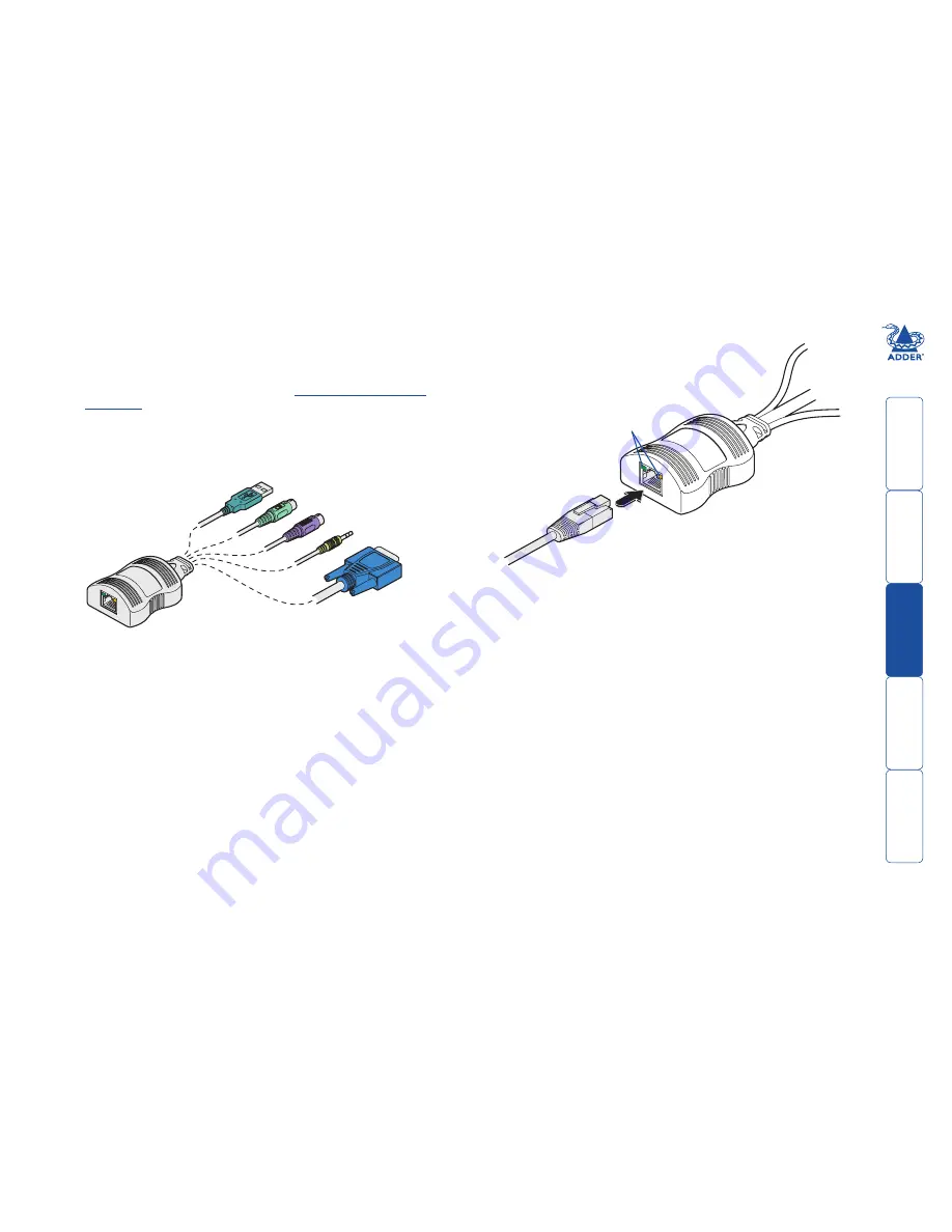
2 Locate the required CAM and attach its video, keyboard and mouse (PS/2-
style or USB) and optional audio connectors to the relevant sockets on the
computer system.
4 Attach the connector of the cable run to the socket of
the CAM. The other end of the cable run will attach to
the remote X100 module.
PS/2-style.keyboard
Audio
Video
USB.keyboard/mouse
PS/2-style.mouse
A range of different
connector combinations
are made available
by the various CAM
formats
Computer
Access
Module
Category 5, 5e or 6 cable
to X00 module
Green indicator - power present
Yellow indicator - signal activity
Note: CAMs derive power from the
computer system via either the PS/2-style
keyboard connector or USB connector.
3 Lay a suitable length of category 5, 5e or 6 cabling between the computer
system and the remote peripherals - see Cable length advice.


