IP482 Industrial I/O Pack User’s Manual Counter Timer Module
___________________________________________________________________
________________________________________________________________________________________
Acromag, Inc. Tel:248-295-0310 Fax:248-624-9234 Email:[email protected] http://www.acromag.com
41
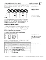
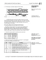
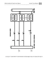
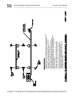
4. The following is a waveform diagram of this example.
i
i
Output
InB
InC
InA
Interrupts
The Gate-Off signal is used in this example to pause the counter.
While the Gate-Off signal is non-active (logic high), the counter and output
will remain constant. Additionally, the output pulse is active for 1.75
s upon
the detection of the final event. For further information, see the Event
Counting Operation description.
Frequency Measurement Operation Example
The objective for this example is to use the Frequency Measurement
Operation using 16-bit Counter 7. The enable signal and the signal
measured are active high. Additionally, the counter has an active low
External Trigger. The output of the counter is active low and interrupts and
debounce are enabled. Assume the enable pulse has a duration of 50
s.
1. Connect the inputs/output to the following pins (unpowered):
Pin # Connection
Description
7
In7_A(+)
Enable Input
17
In7_B(+)
Signal Input
27
In7_C(+)
Ext. Trigger
39
Out7(+)
Output
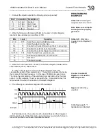
2. Write the following information, BDA4H, to Counter 7 Control Register
located at base address plus an offset of 14H.
Bits
Logic
Operation
2,1,0
100
Sets the counter to Frequency Measurement.
3
0
Sets the output to active low.
5,4
10
Sets the Enable Pulse input (InA) to active high.
7,6
10
Enables the Signal input (InB) to active high.
9,8
01
Enables the external Trigger Input (InC) to active low.
12,11,10
111
Sets the counter to Frequency Measurement mode.
13
1
Enables input debounce on InA, InB, and InC.
14
0
Not used.
15
1
Enables interrupts.
PROGRAMMING
EXAMPLES
In the figure
each “i”
represents an interrupt
Figure 3.5:
Event Counting
waveform
Table 3.26:
Frequency
Measurement Pin
Assignments for Counter 7
Note: Make sure all inputs
and outputs are properly
grounded.
Table 3.27:
Frequency
Measurement Control Register
7 Settings

