


-
-
58
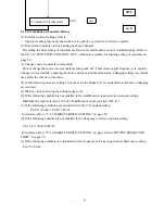
FREQUENCY REFERENCE INPUT
Note: Frequency reference gain (Pn-22) and frequency reference bias (Pn-23) can be changed while
running in DRIVE mode.
Note: How to calculate gain
X =
a
b
100
−
… (1)
G = 10X+b … (2)
X is obtained from equation (1)
X =
8
.
0
10
100
−
= 112.5
G is obtained by substituting X
obtained in equation (1) to equation
(2).
G = 112.5 + 10 = 122.5=123
a: Reference input ratio at 100%
frequency since it is 100% speed
(60 Hz) at 16.8mA in this
example, the following equation
is established.
mA
4
mA
20
mA
4
mA
8
.
16
−
−
=0.8a =0.8
b: Bias level (%)
Since it is 10% (6Hz) at
frequency requence input 4mA in
this example, the following
equation is established.
b = 10
G: gain set value
123 in this example
2.4.2 Calibration of Frequency Meter
Calibration of frequency meter or ammeter connected to the inverter can be performed even without
providing a calibration resistor.
<Example>When the frequency meter specifications are 3V
For instrumentation input of 4 to 20 mA , the amount should be
adjusted at startup. Maximum frequency should be adjusted.
Application Example


