


-
-
10
(2)
Run by analog operator
ANALOG OPERATOR
(JNEP- -14)
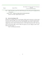
Fig 1.3 Standard Wiring Diagram (Analog Operator)
Notes:
1. Indicates shielded leads and p twisted-pair shielded leads.
2.External terminal (10) of +12V has maximum output current capacity of 20 mA.
3.Terminal Symbols: shows main circuit; shows control circuit.
*Set thermal overload relay between braking resistor and inverter when using braking resistor (type
ERF-150WJ) to protect braking resistor from overheating.
Also, use sequencer to break power supply side on thermal overload relay trip contact when using braking
resistor.
ANALOG OUTPUT
RESET
STOP
FWD RUN
SEQUENCE COMMON (0V)
SHIELDEDTERMINAL
SPEED SETTING POWER 12V 20mA
SPEED REF. 0 - 10V (20k
Ω
)
4 - 20mA (250
Ω
)
0V
7200M3
(R)
(S)
(T)
(U)
IM
(V)
(W)
E
MOTOR
1
2
3
12
11
7
8
11
13
14
6
P
0V
FWD RUN/STOP
2k
Ω
0 to +10V
B1/P
B2
P
B
BRAKING RESISTOR UNIT (OPTION)
(R)
(S)
(T)
GROUNDING
POWER SUPPLY
Only terminal R,S
For single phase series
MULT1-FUNCION
CONTACT INPUT
MASTER
FREQUENCY REF
9
10
MULTI-FUNCTION OUTPUT
OPEN COLLECTOR 1
MULTI-FUNCTION OUTPUT
OPEN COLLECTOR 2


