


-
-
15
NOTE
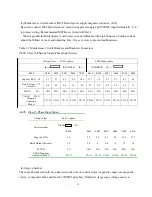
Lead size should be determined considering voltage drop of leads.Voltage drop can be obtained by the
following equation:select such lead size that voltage drop will be within 2% of normal rated voltage.
Phase-to-phase voltage drop(V)=
√
3× lead resistance(ohm/km)
×
wiring distance(m)
×
current(A) ÷ 10
³
˙
Insertion of power supply coordination AC reactor
When the power supply capacity exceeds 600 KVA, connect an AC reactor at the inverter input side for
power supply coordination. This reactor is also effective for power factor improvement of the power
supply.
˙
Wiring length between inverter and motor
If total wiring distance between inverter and motor is excessively long and inverter carrier frequency
(main transistor switching frequency) is high, harmonic leakage current from the cable willincrease to
affect the inverter unit or peripheral devices. If the wiring distance between inverter and motor is long,
reduce the in verter carrier frequency as shown below. Carrier frequency can be set by constant Pn-40.
For details, refer to “CARRIER FREQUENCY SETTING” on page 89. Carrier frequency is set to 10
KHz at the factory prior to shipping.
Wiring Distance between
Inverter and motor
Up to30 m
Up to50 m
Up to 100 m
100 m or
more
Allowable Carrier
Frequency (Constant Pn40 Set Value)
15KHz or
less(6)
10KHz or
less(4)
5KHz or
less(2)
2.5KHz or
less(1)


