Acer V551 (new) CRT Monitor Service Guide
Chapter 2 Circuit Operation Theory
17
Confidence and Property
ACER V551 POWER SUPPLY CIRCUIT OPERATION THEORY
(1) Brief :
Acer V551 is equipped with a current mode, constant frequency, synchronous, using fly back
switching mode power supply circuit,(The operating frequency won't vary with the change of input
voltage or output load. This means synchronous with monitor .) In abbrev, the SMPS or SPS.
Input :
90VAC - 264V AC ( full range)
Output : +50V
0.9A
39.15W
+75V
0.07A
5.25W
+12V
0.76A
9.12W
+ 6.5V
0.6A
3.9 W
Total output power : 62W
(2) Circuit Analysis
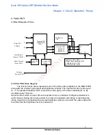
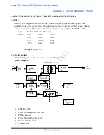
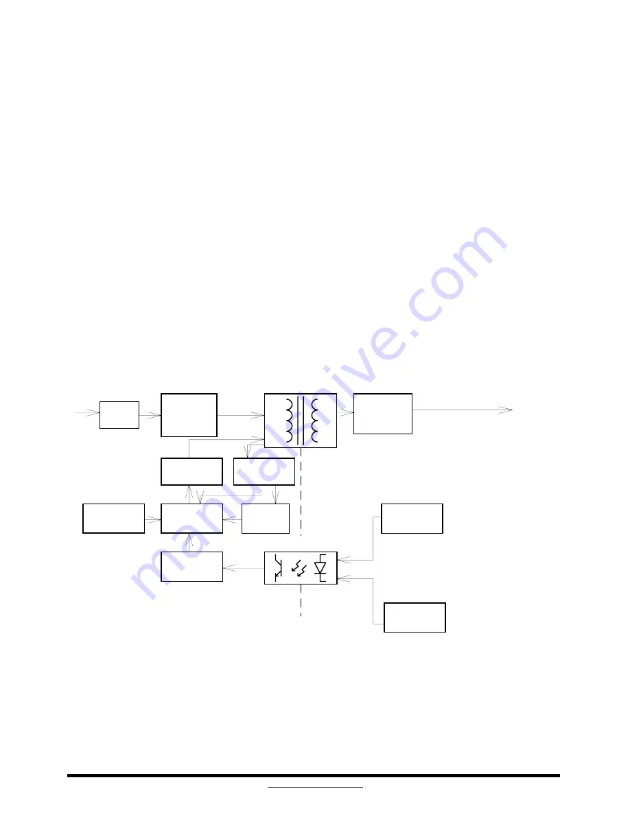
The block diagram is shown as follow , is divided into 13 portions
Block Diagram
Secondary
Rectifier &
Filter
V-Sync
Detector
CKT
Transformer
photo coupler
Bridge
Rectifier
&
Filter
power
MOSFET
& snubber ckt
PWM
controller
control
switch
on/off
EMI
filter
ext sync
Trigger
CKT
Line
Input
Feedback
CKT
DCV
output
1
11
1
2
22
2
7
4
44
4
3
33
3
1
3
1
3
1
3
1
3
8
88
8
5
55
5
Rectifier &
Filter CKT
6
66
6
1
2
1
2
1
2
1
2
9
EPS 1
Detector
CKT
1
0
1
0
1
0
1
0
11
11
11
11
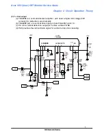
1. EMI filter CKT
2. Power SW & Rectifier, filter CKT
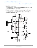
3. PWM controller
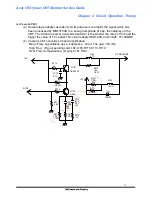
4. Power Mosfet & Snubber CKT
5. Rectifier & Filter CKT
6. Feedback CKT

