Acer V551 (new) CRT Monitor Service Guide
Chapter 2 Circuit Operation Theory
3
Confidence and Property
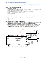
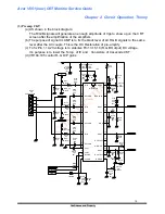
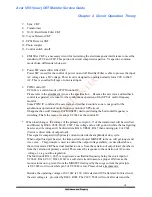
(2) Autosync Deflection Controller--TDA4857
2.1 pin 1 is AFC feedback .
2.2 pin XRAY: if V XRAY > threshold (6.25V typical) switches the whole IC into protection mode.
2.3 pin 3,4,5,6,8 for B+ control function block.
2.4 pin 11(EWDRV) is a parabolic waveform used for pincushion correction
2.5 pin 16 generates video claming & blanking pulse.
2.6 pin 18,19 is I2C data.
2.7 pin 21 V-regulation.
2.8 the resistor from pin 28 (HREF) to ground determines the maximum oscillator frequency.
2.9 the resistor from pin 27 (HBUF) to pin 28 defines the frequency range.
2.10 pin 31 H-regulation.
2.11 pin 32 focus.
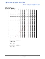
(3) X-ray protection & AFC(Auto Frequency Control)
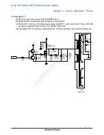
(a) AFC in other words is HFLB (Horizontal Flyback) IC201 pin1, its for synchronize the
second stage (horizontal deflection) with first stage (input signal H-sync.).
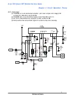
(b) TDA4858 pin2 sense the voltage separated by R217, R218 and R219 from FBT pin9 40V. The
TDA 4857 pin2 trigger voltage is 6.14V. When the FBT pin9 40V increase to let the R219
voltage drop achieve 6.14V, the TDA4857 will shutdown. In the time H.V.=28.5KV.
HSMOD
VSMOD
FOCUS
HUNLOCK
SCL
SDA
ASCOR
VCC DGND
SGND
HDRY
PGND
HPLL2
BDRV
HFLB
32
31
30
29
28
27
26
25
24
23
22
21
20
19
18
17
CLBL
HSYNC
VSYNC
VOUT1
VOUT2
EWDRV
VAGC
VCAP
VREF
HPLL1
HBUF HREF
HCAP
BIN
BSENS
BOP
XRAY
161514131211
10
9
8 7
6
5
4
3 2 1
+
IC201
R218
R217
R219
C205
R220
R222
TDA4857
51K
(1%)
120K
(1%)
23.2K
(1%)
25V
47U
(EL)
2.7K
1/4W
27K
+40V
HFLB
AFC
TP4
TP3

