Acer V551 (new) CRT Monitor Service Guide
Chapter 2 Circuit Operation Theory
5
Confidence and Property
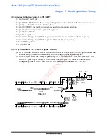
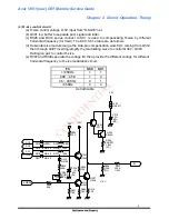
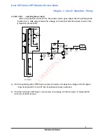
(5) Horizontal output circuit
(a) C321 couple the HDRV wave form from TDA4857 pin7 to Q315 for switching signal
and get the energy by R335 and R332 series, then through the driver transformer T301
couple the driver wave form to horizontal transistor Q310 via R336 at plus duty and via
D312 at minus duty.
(b) While the horizontal transistor Q310 switching a cycle, the energy provided from FBT
T303 pin6 B+ be stored in horizontal deflection yoke and tunning capacitor C314. The
deflection sawtooth current through horizontal deflection yoke was generated during
the Q310 at ON cycle provides the plus part and during Q310 at latter OFF cycle
provides the minus part through the flyback diode D307.
(c) R333 and C318 series is a snubber circuit to inhibit spike.
(d) C324, R329, D313 and D310 is used to compensate the cross-over distortion when the
D307 OFF Q310 ON.
2
1
2
3
1
+
10
2
G2
HV
FOCUS
8
3
9
5
6
1
12
11
6
5
4
3
1
+
R313
Q310
H-DY
C324
D307
C313
C318
C339
C315
C319
R332
R335
R311
R337
R333
R338
R336
R329
D313
R376
D310
D312
D311
D323
J303
L303
T303
T301
Q315
C314
C321
L302
(OPEN)
1/2W
BU2508AF
20.60047.104
0.22U
100V
(PE)
FMP-2FU
(D)
1KV
(OPEN)
(D)
500V
470P
100V
0.01U
(PE)
6800P
630V
(PPN)
50V
1U
(EL)
47
1/4W
1/2W
470
300
1/2W
33
1/4W
1/4W
510
(OPEN)
0.82
2W
(FS)
1/4W
22
1N4148
(OPEN)
RGP10J
1N5817
1N4148
1N4003
(JUMPER)
19.40108.011
19.70060.001
(19.20079.011)
C2235
4000P
1.5KV
(PPSH)
50V
10U
(EL)
(LIN-COIL)
19.50059.001
HDRV
B+
+50V

