Acer V551 (new) CRT Monitor Service Guide
Chapter 2 Circuit Operation Theory
18
Confidence and Property
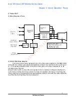
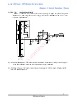
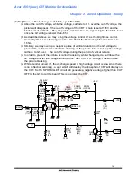
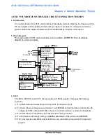
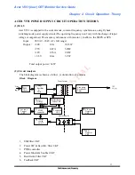
7. Sync. CKT
8. Transformer
9. 10-12: Rectifier & Filter CKT
10. V-sync Detector CKT
11. EPS1 Detector CKT
12. Photo coupler
13. Control switch on/off
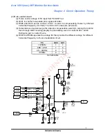
1. EMI filter CKT is a necessary circuit for restraining the electromagnetic interference to meet the
standard of FCC and FTZ. This portion of circuit comprised capacitor, Y capacitor, common
mode choke, differential choke, etc.
2. Power SW and rectifier filter CKT:
Power SW is used for the control of power on and off Rectifier Filter is able to process the input
AC voltage into a DC voltage, This circuit is designed to operate normally form 90V to 264V
AC. This is so called full rage or universal input.
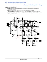
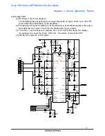
3. PWM control IC
UC3842 is a current mode of PWM control IC.
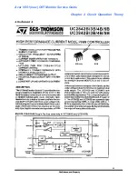
Please refer to the attachment A to see the specification. Because the saw wave and feedback
control is separated, it is ideal for the synchronous operation of the SPS of multi-frequency
monitor.
Some PWM IC combines the saw wave and feedback control as one is not good for the
synchronous operation of multi-frequency monitor's SPS circuit.
It happens the on-off transistor (or MOSFET) destroyed during the horizontal frequency is
switching. That's the reason we adopt UC3842 as the control IC.
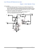
* When load changes, the voltage of the primary coil (pin 6-7) of the transformer will be rectified
and filtered by D608, C608, D607, C607. This voltage value will go down while the load getting
heavier and it's voltage will be divided via R616, VR601, R617 then entering pin 2 of C601
(Verror is direct ratio of output load).
This signal is compared with primary current to decide the amplitude of duty cycle.
When output load gets heavier, the time period of power MOSFET turns on will get longer and
vice versa. This principle is used to control the output voltage stablely, As described above,
the current mode CKT has a dual feedback, one is from the variation of output load, the other is
from the variation of primary current, This causes the response to the variation of AC source
voltage, i.e. a good line regulation.
The function of R613, C615 is to generate a oscillation frequency being the clock input of
UC3842, R614, C617, D611, D612 is a soft start circuit to assure a proper ON time as the
monitor turns on to prevent from the MOSFET destroyed by the surge current the principle
is UC3842 won't work while pin 1 of UC3842 is low. Please check attachment A.
Besides, the operating voltage of UC3842 is 16V while start and 10V after start. In this circuit,
the start voltage is provided by R602, R603. The C607, T601 will work after start and the

