Chapter 3
73
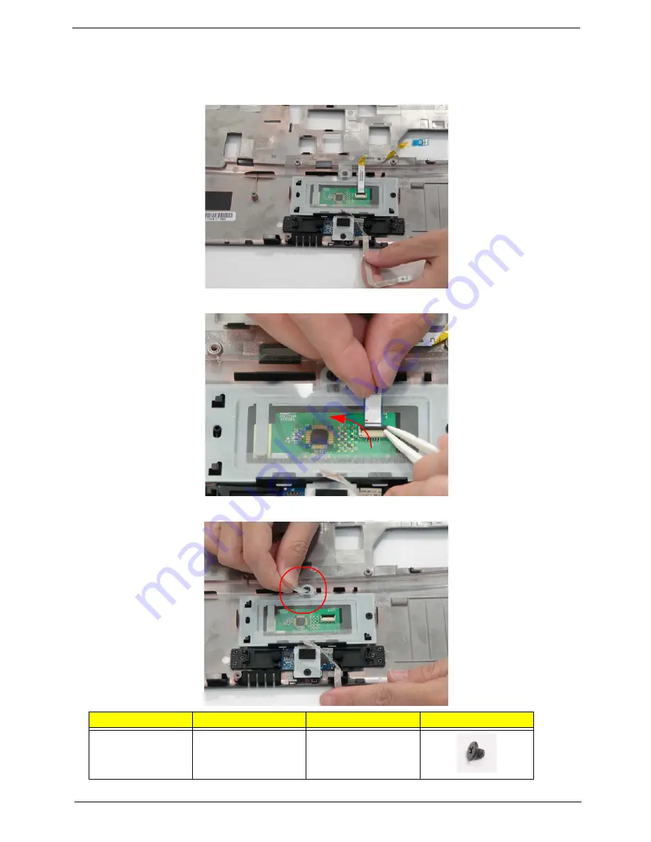
Removing the Touch Pad Bracket
1.
See “Removing the Upper Cover” on page 67.
2.
Peel back the Finger Print Reader FFC to expose the Touch Pad connector.
3.
Disconnect the Touch Pad FFC from the Touch Pad board.
4.
Lift up the covering and remove the securing screw.
Step
Size
Quantity
Screw Type
Touch Pad Bracket
M2.5*3 (NL)
2
Содержание TravelMate 4730 Series
Страница 6: ...VI ...
Страница 10: ...X Table of Contents ...
Страница 14: ...4 Chapter 1 System Block Diagram ...
Страница 34: ...24 Chapter 1 ...
Страница 51: ...Chapter 2 41 3 Reboot the system and key in the selected string qjjg9vy 07yqmjd etc for the BIOS user password ...
Страница 52: ...42 Chapter 2 ...
Страница 60: ...50 Chapter 3 7 Remove the WLAN cover as shown ...
Страница 95: ...Chapter 3 85 7 Lift the Thermal Module clear of the Mainboard ...
Страница 114: ...104 Chapter 3 3 Connect the RJ 11 cable to the modem module as shown ...
Страница 118: ...108 Chapter 3 2 Replace the two securing screws ...
Страница 122: ...112 Chapter 3 2 Connect the seven cables on the mainboard as shown B C D E F G A ...
Страница 128: ...118 Chapter 3 3 Turn the computer over and replace the five securing screws ...
Страница 175: ...Chapter 6 165 ...
Страница 184: ...Appendix A 174 ...
Страница 188: ...178 Appendix B ...
Страница 190: ...180 Appendix C ...
Страница 193: ...183 Wireless Function Failure 136 WLAN Board 52 ...
Страница 194: ...184 ...


