


142
Chapter 4
POST Codes Tables
These tables describe the POST codes, drivers, and keys for the POST.
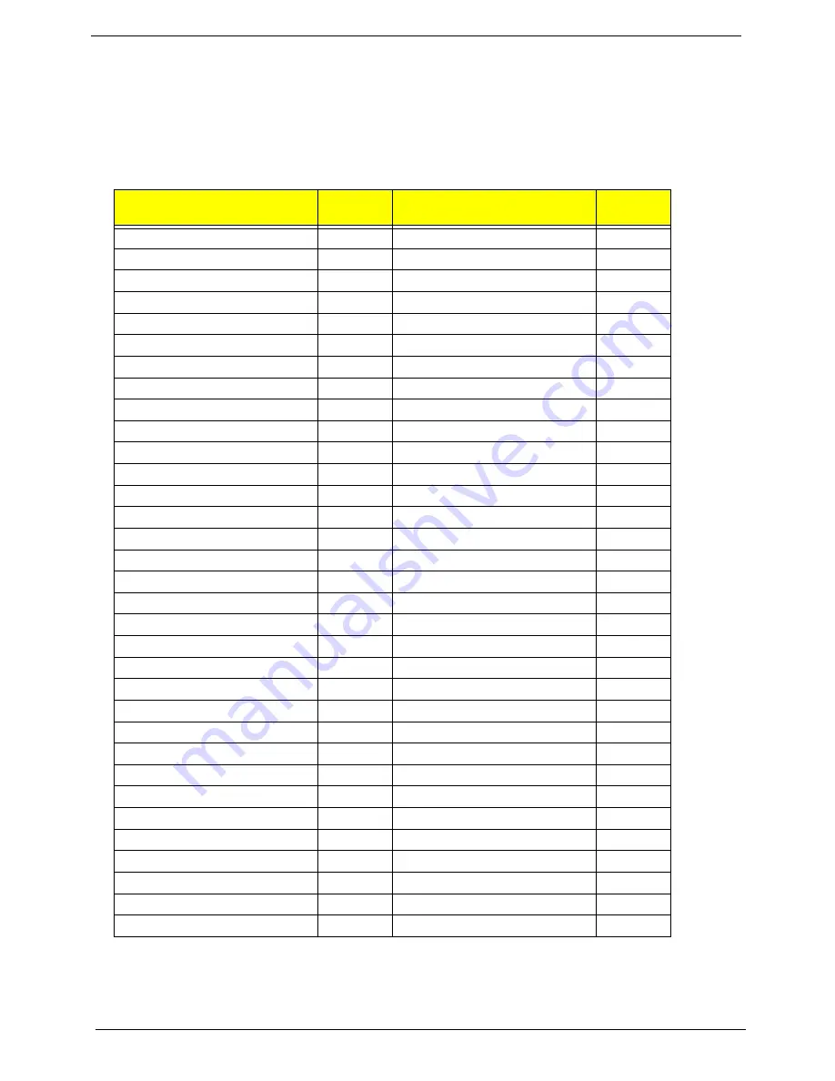
Port 80 POST Codes
The following table details the Port 80 POST codes and drivers used in the POST.
Driver Name
Port 80
Code
Driver Name
Port 80
Code
PeiEventLog
01
CpuIo
3E
OemServices
02
Cf9Reset
3F
SioInit
03
PcRtc
40
MonoStatusCode
04
StatusCode
41
PentiumMCpuPeim
08
Variable
42
PlatformStage1
09
SmmVariable
CF
Variable
0A
EmuVariable
43
IchInit
0B
TcgDxe
A2
PlatformStage2
0D
PhysicalPresence
A3
IchSmbusArpDisabled
0E
TpmDriver
AE
ClockGen
12
TcgSmm
AE
OpPresence
13
PhysicalPresenceReadyToBoot
AE
TcgPei
14
DataHubRecordPolicy
AD
FindFv
15
Undi
86
DxeIpl
2F
SNP
90
LightMemoryInit
10
BC
91
S3ResumeSoftSmi
11
PxeDhcp4
92
Crc32SectionExtract
31
Ebc
93
OemServices
A4
IsaBus
4D
EventLog
A5
IsaSerial
4E
ScriptSave
32
Ps2Mouse
6D
AcpiS3Save
33
IdeBus
4F
SmartTimer
34
LightPciBus
50
JpegDecoder
35
UsbBot
6E
PcxDecoder
36
UsbCbi0
6F
PlatformBds
8A
UsbCbi1
70
MpCpu
37
UsbKb
71
LegacyMetronome
38
UsbMassStorage
72
FtwLite
39
UsbMouse
74
Runtime
3A
Ehci
8F
MonotonicCounter
3B
Uhci
73
WatchDogTimer
3C
UsbBus
75
SecurityStub
3D
SmmBase
C2
Содержание TravelMate 4730 Series
Страница 6: ...VI ...
Страница 10: ...X Table of Contents ...
Страница 14: ...4 Chapter 1 System Block Diagram ...
Страница 34: ...24 Chapter 1 ...
Страница 51: ...Chapter 2 41 3 Reboot the system and key in the selected string qjjg9vy 07yqmjd etc for the BIOS user password ...
Страница 52: ...42 Chapter 2 ...
Страница 60: ...50 Chapter 3 7 Remove the WLAN cover as shown ...
Страница 95: ...Chapter 3 85 7 Lift the Thermal Module clear of the Mainboard ...
Страница 114: ...104 Chapter 3 3 Connect the RJ 11 cable to the modem module as shown ...
Страница 118: ...108 Chapter 3 2 Replace the two securing screws ...
Страница 122: ...112 Chapter 3 2 Connect the seven cables on the mainboard as shown B C D E F G A ...
Страница 128: ...118 Chapter 3 3 Turn the computer over and replace the five securing screws ...
Страница 175: ...Chapter 6 165 ...
Страница 184: ...Appendix A 174 ...
Страница 188: ...178 Appendix B ...
Страница 190: ...180 Appendix C ...
Страница 193: ...183 Wireless Function Failure 136 WLAN Board 52 ...
Страница 194: ...184 ...


