VIII
Table of Contents
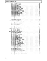
Removing the Power Board . . . . . . . . . . . . . . . . . . . . . . . . . . . . . . . . . . . . . . . .61
Removing the Launch Board . . . . . . . . . . . . . . . . . . . . . . . . . . . . . . . . . . . . . . .62
Removing the Antenna . . . . . . . . . . . . . . . . . . . . . . . . . . . . . . . . . . . . . . . . . . . .63
Removing the LCD Module . . . . . . . . . . . . . . . . . . . . . . . . . . . . . . . . . . . . . . . . .65
Removing the Upper Cover . . . . . . . . . . . . . . . . . . . . . . . . . . . . . . . . . . . . . . . .67
Removing the Finger Print Reader . . . . . . . . . . . . . . . . . . . . . . . . . . . . . . . . . . .71
Removing the Touch Pad Bracket . . . . . . . . . . . . . . . . . . . . . . . . . . . . . . . . . . .73
Removing the Left Speaker Module . . . . . . . . . . . . . . . . . . . . . . . . . . . . . . . . . .74
Removing the Right Speaker Module . . . . . . . . . . . . . . . . . . . . . . . . . . . . . . . . .76
Removing the Bluetooth Module . . . . . . . . . . . . . . . . . . . . . . . . . . . . . . . . . . . . .77
Removing the Modem Module . . . . . . . . . . . . . . . . . . . . . . . . . . . . . . . . . . . . . .78
Removing the Mainboard . . . . . . . . . . . . . . . . . . . . . . . . . . . . . . . . . . . . . . . . . .79
Removing the USB Board . . . . . . . . . . . . . . . . . . . . . . . . . . . . . . . . . . . . . . . . . .82
Removing the RJ-11 Port . . . . . . . . . . . . . . . . . . . . . . . . . . . . . . . . . . . . . . . . . .83
Removing the Thermal Module . . . . . . . . . . . . . . . . . . . . . . . . . . . . . . . . . . . . . .84
Removing the CPU . . . . . . . . . . . . . . . . . . . . . . . . . . . . . . . . . . . . . . . . . . . . . . .86
Removing the VGA Module . . . . . . . . . . . . . . . . . . . . . . . . . . . . . . . . . . . . . . . .87
LCD Module Disassembly Process . . . . . . . . . . . . . . . . . . . . . . . . . . . . . . . . . . . . . .88
LCD Module Disassembly Flowchart . . . . . . . . . . . . . . . . . . . . . . . . . . . . . . . . .88
Removing the LCD Bezel . . . . . . . . . . . . . . . . . . . . . . . . . . . . . . . . . . . . . . . . . .89
Removing the Inverter Board . . . . . . . . . . . . . . . . . . . . . . . . . . . . . . . . . . . . . . .90
Removing the Camera Module . . . . . . . . . . . . . . . . . . . . . . . . . . . . . . . . . . . . . .91
Removing the LCD Panel . . . . . . . . . . . . . . . . . . . . . . . . . . . . . . . . . . . . . . . . . .93
Removing the LCD Brackets and FPC Cable . . . . . . . . . . . . . . . . . . . . . . . . . . .94
Removing the Antennas . . . . . . . . . . . . . . . . . . . . . . . . . . . . . . . . . . . . . . . . . . .95
Removing the MIC Module . . . . . . . . . . . . . . . . . . . . . . . . . . . . . . . . . . . . . . . . .96
LCD Module Reassembly Procedure . . . . . . . . . . . . . . . . . . . . . . . . . . . . . . . . . . . . .97
Replacing the LCD Panel . . . . . . . . . . . . . . . . . . . . . . . . . . . . . . . . . . . . . . . . . .97
Replacing the LCD Bezel . . . . . . . . . . . . . . . . . . . . . . . . . . . . . . . . . . . . . . . . .101
Main Module Reassembly Procedure . . . . . . . . . . . . . . . . . . . . . . . . . . . . . . . . . . . .102
Replacing the VGA Module . . . . . . . . . . . . . . . . . . . . . . . . . . . . . . . . . . . . . . . .102
Replacing the CPU . . . . . . . . . . . . . . . . . . . . . . . . . . . . . . . . . . . . . . . . . . . . . .102
Replacing the Thermal Module . . . . . . . . . . . . . . . . . . . . . . . . . . . . . . . . . . . . .103
Replacing the RJ-11 Port . . . . . . . . . . . . . . . . . . . . . . . . . . . . . . . . . . . . . . . . .103
Replacing the Mainboard . . . . . . . . . . . . . . . . . . . . . . . . . . . . . . . . . . . . . . . . .105
Replacing the Modem Module . . . . . . . . . . . . . . . . . . . . . . . . . . . . . . . . . . . . .106
Replacing the Bluetooth Board . . . . . . . . . . . . . . . . . . . . . . . . . . . . . . . . . . . . .107
Replacing the Right Speaker Module . . . . . . . . . . . . . . . . . . . . . . . . . . . . . . . .107
Replacing the Launch Board . . . . . . . . . . . . . . . . . . . . . . . . . . . . . . . . . . . . . . .109
Replacing the Finger Print Reader . . . . . . . . . . . . . . . . . . . . . . . . . . . . . . . . . .110
Replacing the Touch Pad Bracket . . . . . . . . . . . . . . . . . . . . . . . . . . . . . . . . . .110
Replacing the Left Speaker Module . . . . . . . . . . . . . . . . . . . . . . . . . . . . . . . . .111
Replacing the Upper Cover . . . . . . . . . . . . . . . . . . . . . . . . . . . . . . . . . . . . . . . .111
Replacing the LCD Module . . . . . . . . . . . . . . . . . . . . . . . . . . . . . . . . . . . . . . . .113
Replacing the Antenna Cables . . . . . . . . . . . . . . . . . . . . . . . . . . . . . . . . . . . . .115
Replacing the Keyboard . . . . . . . . . . . . . . . . . . . . . . . . . . . . . . . . . . . . . . . . . .117
Replacing the Switch Cover . . . . . . . . . . . . . . . . . . . . . . . . . . . . . . . . . . . . . . .117
Replacing the WLAN Module . . . . . . . . . . . . . . . . . . . . . . . . . . . . . . . . . . . . . .119
Replacing the Hard Disk Drive Module . . . . . . . . . . . . . . . . . . . . . . . . . . . . . . .119
Replacing the DIMM Modules . . . . . . . . . . . . . . . . . . . . . . . . . . . . . . . . . . . . . .120
Replacing the ODD Module . . . . . . . . . . . . . . . . . . . . . . . . . . . . . . . . . . . . . . .121
Replacing the Lower Covers . . . . . . . . . . . . . . . . . . . . . . . . . . . . . . . . . . . . . . .121
Replacing the NewCard and SD Card Trays . . . . . . . . . . . . . . . . . . . . . . . . . .122
Содержание Extensa 4630G
Страница 6: ...VI...
Страница 10: ...X Table of Contents...
Страница 14: ...4 Chapter 1 System Block Diagram...
Страница 34: ...24 Chapter 1...
Страница 51: ...Chapter 2 41 3 Reboot the system and key in the selected string qjjg9vy 07yqmjd etc for the BIOS user password...
Страница 52: ...42 Chapter 2...
Страница 60: ...50 Chapter 3 7 Remove the WLAN cover as shown...
Страница 95: ...Chapter 3 85 7 Lift the Thermal Module clear of the Mainboard...
Страница 114: ...104 Chapter 3 3 Connect the RJ 11 cable to the modem module as shown...
Страница 118: ...108 Chapter 3 2 Replace the two securing screws...
Страница 122: ...112 Chapter 3 2 Connect the seven cables on the mainboard as shown B C D E F G A...
Страница 128: ...118 Chapter 3 3 Turn the computer over and replace the five securing screws...
Страница 175: ...Chapter 6 165...
Страница 184: ...Appendix A 174...
Страница 188: ...178 Appendix B...
Страница 190: ...180 Appendix C...
Страница 193: ...183 Wireless Function Failure 136 WLAN Board 52...
Страница 194: ...184...


