


Chapter 4
125
No Display Issue
If the
Display
doesn’t work, perform the following actions one at a time to correct the problem. Do not replace
a non-defective FRUs:
No POST or Video
If the POST or video doesn’t display, perform the following actions one at a time to correct the problem.
1.
Make sure that the internal display is selected. On this notebook model, switching between the internal
display and the external display is done by pressing
Fn+F5
. Reference Product pages for specific model
procedures.
2.
Make sure the computer has power by checking at least one of the following occurs:
•
Fans start up
•
Status LEDs light up
If there is no power, see “Power On Issue” on page 124.
3.
Drain any stored power by removing the power cable and battery and holding down the power button for
10 seconds. Reconnect the power and reboot the computer.
4.
Connect an external monitor to the computer and switch between the internal display and the external
display is by pressing
Fn+F5
(on this model).
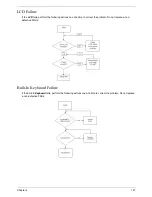
If the POST or video appears on the external display, see “LCD Failure” on page 127.
5.
Disconnect power and all external devices including port replicators or docking stations. Remove any
memory cards and CD/DVD discs. Restart the computer.
If the computer boots correctly, add the devices one by one until the failure point is discovered.
6.
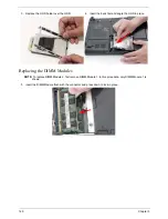
Reseat the memory modules.
7.
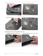
Remove the drives (see “Disassembly Process” on page 44).
8.
If the Issue is still not resolved, see “Online Support Information” on page 179.
Содержание Extensa 4630G
Страница 6: ...VI...
Страница 10: ...X Table of Contents...
Страница 14: ...4 Chapter 1 System Block Diagram...
Страница 34: ...24 Chapter 1...
Страница 51: ...Chapter 2 41 3 Reboot the system and key in the selected string qjjg9vy 07yqmjd etc for the BIOS user password...
Страница 52: ...42 Chapter 2...
Страница 60: ...50 Chapter 3 7 Remove the WLAN cover as shown...
Страница 95: ...Chapter 3 85 7 Lift the Thermal Module clear of the Mainboard...
Страница 114: ...104 Chapter 3 3 Connect the RJ 11 cable to the modem module as shown...
Страница 118: ...108 Chapter 3 2 Replace the two securing screws...
Страница 122: ...112 Chapter 3 2 Connect the seven cables on the mainboard as shown B C D E F G A...
Страница 128: ...118 Chapter 3 3 Turn the computer over and replace the five securing screws...
Страница 175: ...Chapter 6 165...
Страница 184: ...Appendix A 174...
Страница 188: ...178 Appendix B...
Страница 190: ...180 Appendix C...
Страница 193: ...183 Wireless Function Failure 136 WLAN Board 52...
Страница 194: ...184...


