


32
Chapter 2
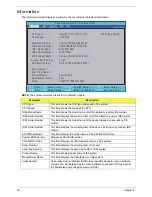
Information
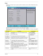
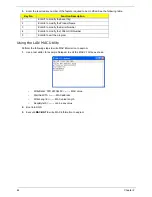
The Information screen displays a summary of your computer hardware information.
NOTE:
The system information is subject to different models.
Parameter
Description
CPU Type
This field shows the CPU type and speed of the system.
CPU Speed
This field shows the speed of the CPU.
IDE0 Model Name
This field shows the model name of HDD installed on primary IDE master.
IDE0 Serial Number
This field displays the serial number of HDD installed on primary IDE master.
IDE1 Serial Number
This field shows the model name of the device installed on secondary IDE
master.
IDE1 Serial Number
This field displays the serial number of the device installed on secondary IDE
master.
ATAPI Model Name
This field displays the model name of the installed ODD drive.
System BIOS Version
Displays system BIOS version.
VGA BIOS Version
This field displays the VGA firmware version of the system.
Serial Number
This field displays the serial number of this unit.
Asset Tag Number
This field displays the asset tag number of the system.
Product Name
This field shows product name of the system.
Manufacturer Name
This field displays the manufacturer of this system.
UUID Number
Universally Unique Identifier (UUID) is an identifier standard used in software
construction, standardized by the Open Software Foundation (OSF) as part of
the Distributed Computing Environment (DCE).
P h o e n i x S e c u r e C o r e ( t m ) S e t u p U t i l i t y
F 1
E S C
H e l p
E x i t
S e l e c t I t e m
S e l e c t M e n u
C h a n g e Va l u e s
S e l e c t
S u b M e n u
E n t e r
F 9
F 1 0
S e t u p D e f a u l t
S a v e a n d E x i t
I n t e l ( R ) C o r e ( T M ) i 3 C P U M 3 3 0 @ 2 . 1 3 G H z
2 1 3 0 M H z
H i t a c h i H T S 5 4 5 0 1 6 B 9 A 3 0 0
0 9 1 2 0 2 P B G K 0 6 1 S H P Z 7 T N
O p t i a r c D V D RW A D - 7 5 8 5 H
V 1 . 0 0
ATi 0 1 2 . 0 2 0 . 0 0 0 . 0 0 0 . 0 3 5 2 5 7
A s p i r e 7 7 4 5
A c e r
3 F 9 d 8 7 8 7 7 F 6 9 4 7 6 3 9 6 8 5
S e r i a l N u m b e r :
C P U Ty p e :
C P U S p e e d :
I D E 0 M o d e l N a m e :
I D E 0 S e r i a l N u m b e r :
I D E 1 M o d e l N a m e : S T 9 1 6 0 3 1 4 A S
I D E 0 S e r i a l N u m b e r : 5 V C C G N Q J
ATA P I M o d e l N a m e :
S y s t e m B I O S Ve r s i o n :
V G A B I O S Ve r s i o n :
A s s e t Ta g N u m b e r :
P r o d u c t N a m e :
M a n u f a c t u r e r N a m e :
U U I D :
F 5 / F 6
Main
Boot
Exit
Security
Information
Содержание ASPIRE 7745
Страница 6: ...VI ...
Страница 10: ...X Table of Contents ...
Страница 40: ...30 Chapter 1 ...
Страница 56: ...46 Chapter 2 ...
Страница 68: ...58 Chapter 3 5 Pull the WLAN module out and away ...
Страница 73: ...Chapter 3 63 5 Remove the ODD bracket 6 Pry the ODD bezel off of the ODD module ...
Страница 83: ...Chapter 3 73 5 Detach the Bluetooth module cable from the module ...
Страница 91: ...Chapter 3 81 4 Lift the thermal module away from the main board ...
Страница 96: ...86 Chapter 3 4 Unlock and disconnect the switch board FFC ...
Страница 101: ...Chapter 3 91 4 Remove the bezel from the LCD module ...
Страница 108: ...98 Chapter 3 5 Pry the right antenna from the casing ...
Страница 111: ...Chapter 3 101 3 Lay the cables around the module edge ...
Страница 115: ...Chapter 3 105 10 Place the LVDS cable into cable guides ...
Страница 118: ...108 Chapter 3 4 Replace the two 2 bezel screws ...
Страница 121: ...Chapter 3 111 2 Using a flat bladed screw driver rotate the CPU locking screw 180 clockwise to secure the CPU in place ...
Страница 123: ...Chapter 3 113 Replacing the RTC Battery 1 Push the RTC battery into the cradle on the mainboard plus side up ...
Страница 129: ...Chapter 3 119 4 Connect the Bluetooth module cable to the main board ...
Страница 131: ...Chapter 3 121 4 Connect the LVDC cable 5 Lay the LVDS cable across the assembly as shown and press down firmly ...
Страница 136: ...126 Chapter 3 6 Connect and lock the Power board FFC ...
Страница 143: ...Chapter 3 133 4 Grasp the tab and slide the HDD firmly into the docking connector ...
Страница 145: ...Chapter 3 135 4 Push the ODD completely into the bay until flush with the lower cover ...
Страница 148: ...138 Chapter 3 ...
Страница 166: ...156 Chapter 4 ...
Страница 288: ...278 Appendix B ...
Страница 290: ...280 ...


