


Chapter 4
155
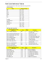
SMM Functions POST Code Table
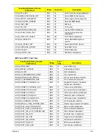
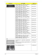
InsydeH2ODDT Debugger POST Code Table
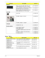
ASL_ENTER_S4
ASL
54
Prepare to enter S4
ASL_ENTER_S5
ASL
55
Prepare to enter S5
ASL_WAKEUP_S1
ASL
E1
System wakeup from S1
ASL_WAKEUP_S3
ASL
E3
System wakeup from S3
ASL_WAKEUP_S4
ASL
E4
System wakeup from S4
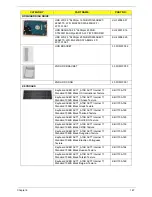
Functionality Name (Include\
PostCode.h)
Phase
Post
Code
Description
SMM_IDENTIFY_FLASH_DEVICE
SMM
0xA0
Identify Flash device in SMM
SMM_SMM_PLATFORM_INIT
SMM
0xA2
SMM service initial
SMM_ACPI_ENABLE_START
SMM
0xA6
OS call ACPI enable function
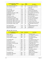
SMM_ACPI_ENABLE_END
SMM
0xA7
ACPI enable function complete
SMM_S1_SLEEP_CALLBACK
SMM
0xA1
Enter S1
SMM_S3_SLEEP_CALLBACK
SMM
0xA3
Enter S3
SMM_S4_SLEEP_CALLBACK
SMM
0xA4
Enter S4
SMM_S5_SLEEP_CALLBACK
SMM
0xA5
Enter S5
SMM_ACPI_DISABLE_START
SMM
0xA8
OS call ACPI disable function
SMM_ACPI_DISABLE_END
SMM
0xA9
ACPI disable function complete
Functionality Name
(Include\ PostCode.h)
PostCode
Description
Used by Insyde debugger
0x0D
Waiting for device connect
Used by Insyde debugger
0xD0
Waiting for device connect
Used by Insyde debugger
0xD1
InsydeH2ODDT Ready
Used by Insyde debugger
0xD2
EHCI not found
Used by Insyde debugger
0xD3
Debug port connect low speed device
Used by Insyde debugger
0xD4
DDT Cable become low speed device
Used by Insyde debugger
0xD5
DDT Cable Transmission Error (Get descriptor fail)
Used by Insyde debugger
0xD6
DDT Cable Transmission Error (Set Debug mode fail)
Used by Insyde debugger
0xD7
DDT Cable Transmission Error (Set address fail)
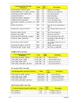
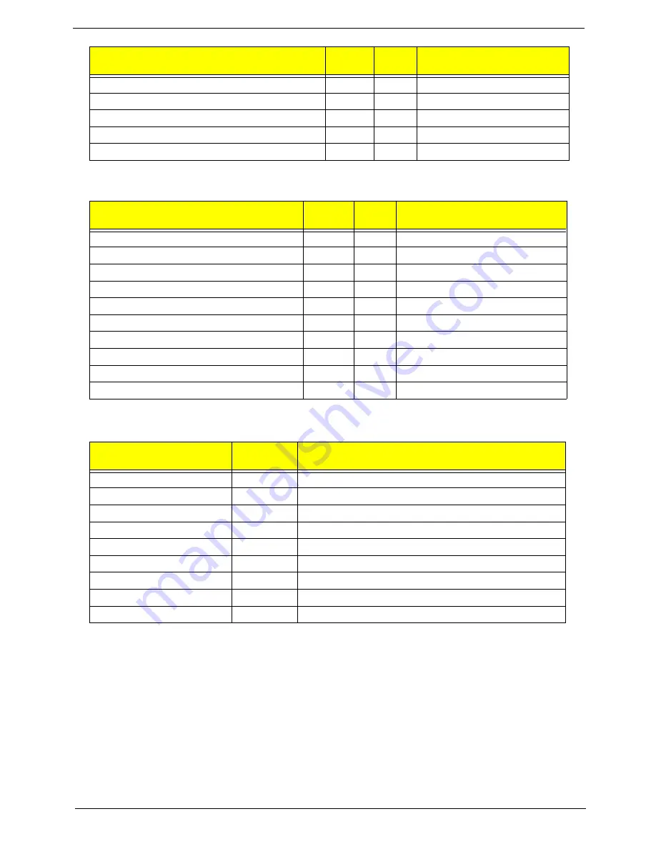
Functionality Name (Include\ PostCode.h)
Phase
Post
Code
Description
Содержание ASPIRE 7745
Страница 6: ...VI ...
Страница 10: ...X Table of Contents ...
Страница 40: ...30 Chapter 1 ...
Страница 56: ...46 Chapter 2 ...
Страница 68: ...58 Chapter 3 5 Pull the WLAN module out and away ...
Страница 73: ...Chapter 3 63 5 Remove the ODD bracket 6 Pry the ODD bezel off of the ODD module ...
Страница 83: ...Chapter 3 73 5 Detach the Bluetooth module cable from the module ...
Страница 91: ...Chapter 3 81 4 Lift the thermal module away from the main board ...
Страница 96: ...86 Chapter 3 4 Unlock and disconnect the switch board FFC ...
Страница 101: ...Chapter 3 91 4 Remove the bezel from the LCD module ...
Страница 108: ...98 Chapter 3 5 Pry the right antenna from the casing ...
Страница 111: ...Chapter 3 101 3 Lay the cables around the module edge ...
Страница 115: ...Chapter 3 105 10 Place the LVDS cable into cable guides ...
Страница 118: ...108 Chapter 3 4 Replace the two 2 bezel screws ...
Страница 121: ...Chapter 3 111 2 Using a flat bladed screw driver rotate the CPU locking screw 180 clockwise to secure the CPU in place ...
Страница 123: ...Chapter 3 113 Replacing the RTC Battery 1 Push the RTC battery into the cradle on the mainboard plus side up ...
Страница 129: ...Chapter 3 119 4 Connect the Bluetooth module cable to the main board ...
Страница 131: ...Chapter 3 121 4 Connect the LVDC cable 5 Lay the LVDS cable across the assembly as shown and press down firmly ...
Страница 136: ...126 Chapter 3 6 Connect and lock the Power board FFC ...
Страница 143: ...Chapter 3 133 4 Grasp the tab and slide the HDD firmly into the docking connector ...
Страница 145: ...Chapter 3 135 4 Push the ODD completely into the bay until flush with the lower cover ...
Страница 148: ...138 Chapter 3 ...
Страница 166: ...156 Chapter 4 ...
Страница 288: ...278 Appendix B ...
Страница 290: ...280 ...


