


Chapter 1
29
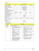
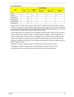
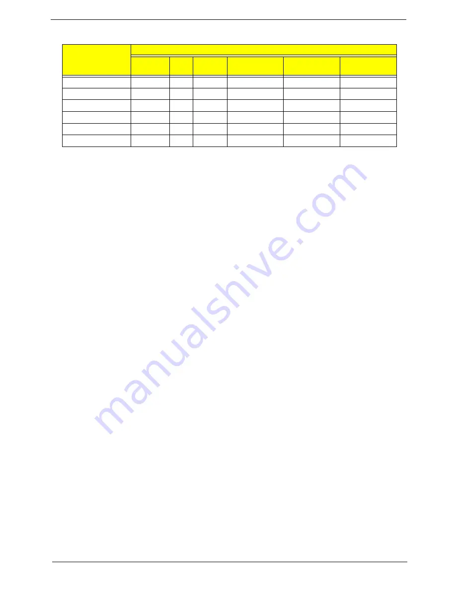
Power Specification
*Mechanical off is a condition where all power except the RTC battery has been removed from the system.
1. Initial to On state: When the AC adapter or Battery pack has been plugged into the system, the I WPC781
will be reset and initial all output pins then the system goes into Initial state and waiting for power on event. If
the power button is pressed then the system will go into the ON state.
2. ON to Standby state: The system will go into the Standby state when HM55 receives the POS command.
3. ON to Suspend state: The system will go into Suspend state when HM55 receives the S2R command.
4. ON to Hibernate state: The system will go into Hibernate state when HM55 receives the S2D command.
5. ON to Soft Off state: The system will go into Soft Off state when HM55 receives the Soft off command.
6. Standby to ON state: The system will go into ON state when the system receives any wake up events, for
example, keyboard, mouse.
7. Suspend to ON state: The system will go into ON state when the power button is pressed.
8. Hibernate to ON state: The system will go into ON state when the power button is pressed.
9. Soft Off to ON state: The system will go into ON state when the power button is pressed.
Item
Specification
Initial
On
Stand
by
Suspend
Hibernate
Soft Off
Initial
1
ON (S0)
2
3
4
5
Standby (S1)
6
Suspend (S3)
7
Hibernate (S4)
8
Soft Off (S5)
9
Содержание ASPIRE 7745
Страница 6: ...VI ...
Страница 10: ...X Table of Contents ...
Страница 40: ...30 Chapter 1 ...
Страница 56: ...46 Chapter 2 ...
Страница 68: ...58 Chapter 3 5 Pull the WLAN module out and away ...
Страница 73: ...Chapter 3 63 5 Remove the ODD bracket 6 Pry the ODD bezel off of the ODD module ...
Страница 83: ...Chapter 3 73 5 Detach the Bluetooth module cable from the module ...
Страница 91: ...Chapter 3 81 4 Lift the thermal module away from the main board ...
Страница 96: ...86 Chapter 3 4 Unlock and disconnect the switch board FFC ...
Страница 101: ...Chapter 3 91 4 Remove the bezel from the LCD module ...
Страница 108: ...98 Chapter 3 5 Pry the right antenna from the casing ...
Страница 111: ...Chapter 3 101 3 Lay the cables around the module edge ...
Страница 115: ...Chapter 3 105 10 Place the LVDS cable into cable guides ...
Страница 118: ...108 Chapter 3 4 Replace the two 2 bezel screws ...
Страница 121: ...Chapter 3 111 2 Using a flat bladed screw driver rotate the CPU locking screw 180 clockwise to secure the CPU in place ...
Страница 123: ...Chapter 3 113 Replacing the RTC Battery 1 Push the RTC battery into the cradle on the mainboard plus side up ...
Страница 129: ...Chapter 3 119 4 Connect the Bluetooth module cable to the main board ...
Страница 131: ...Chapter 3 121 4 Connect the LVDC cable 5 Lay the LVDS cable across the assembly as shown and press down firmly ...
Страница 136: ...126 Chapter 3 6 Connect and lock the Power board FFC ...
Страница 143: ...Chapter 3 133 4 Grasp the tab and slide the HDD firmly into the docking connector ...
Страница 145: ...Chapter 3 135 4 Push the ODD completely into the bay until flush with the lower cover ...
Страница 148: ...138 Chapter 3 ...
Страница 166: ...156 Chapter 4 ...
Страница 288: ...278 Appendix B ...
Страница 290: ...280 ...


