


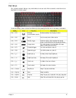


Chapter 1
17
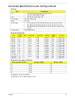
Hardware Specifications and Configurations
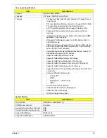
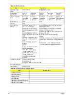
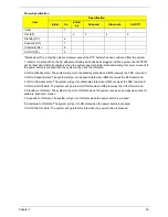
Processor
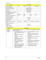
Processor Specifications
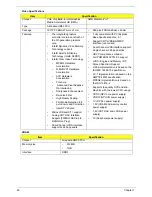
CPU Fan True Value Table (TJ100-CPU)
Throttling 50%: On= 95°C; OFF=93°C
OS shut down at 105°C; H/W shut down at 110°C
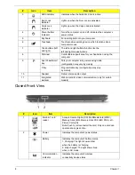
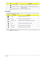
Item
Specification
CPU
•
Intel Calpella (Discrete/UMA: Arrandale with Gfx)
•
Intel PCH: HM55 (4MB SPI ROM)
Type
•
MCP (Multi-Chip Package) CPU
CPU Package
989 pins-rPGA socket
Power
65 Watts
On-die Cache
•
32-KB instruction and 32 -KB data first-level cache (L1) for each core
•
256-KB shared instruction/data second -level cache (L2) for each core
•
Up to 8-MB shared instruction/data last -level cache (L3), shared among
all cores
Front Side Bus
800/1066M/1333Hz
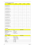
Item
CPU
Speed
Cores
Bus Speed
Cache Size
Package
Core
Voltage
Acer P/N
Ci3330M
2.13
2
330 M
3 MB
PGA988
35W
KC.33001.DMP
Ci3350M
2.26 2
350
M
3
MB
PGA988
35W
KC.35001.DMP
Ci3350M
2.26 2
350
M
3
MB
PGA988
35W
KC.35K01.DMP
Ci3370M
2.4
2
370 M
3 MB
PGA988
35W
KC.37K01.DMP
Ci5430M
2.26
2
430 M
3 MB
PGA988
35W
KC.43001.DMP
Ci5450M
2.4
2
450 M
3 MB
PGA988
35 W
KC.45K01.DMP
Ci5520M
2.24
2
520 M
3 MB
PGA988P
35W
KC.52001.DMP
Ci5540M
2.53
2
540 M
3 MB
PGA988
35W
KC.54001.DMP
Ci7620M
2.66
2
620 M
4 MB
PGA988
35W
KC.62001.QMP
Ci7720QM
1.6
4
720 M
6 MB
PGA988
45W
KC.72001.QMP
Ci7820QM
1.73
4
820 M
8 MB
PGA988
45W
KC.82001.QMP
PMDP6000
1.86
2
3 MB
PGA988
35W
KC.60001.DPP
CPU Temperature (Celsius)
Fan Speed (RPM)
SPL Spec (dBA)
45
2700
31
53
3000
34
65
3350
37
85
3650
40
91
3750
41
Содержание ASPIRE 7745
Страница 6: ...VI ...
Страница 10: ...X Table of Contents ...
Страница 40: ...30 Chapter 1 ...
Страница 56: ...46 Chapter 2 ...
Страница 68: ...58 Chapter 3 5 Pull the WLAN module out and away ...
Страница 73: ...Chapter 3 63 5 Remove the ODD bracket 6 Pry the ODD bezel off of the ODD module ...
Страница 83: ...Chapter 3 73 5 Detach the Bluetooth module cable from the module ...
Страница 91: ...Chapter 3 81 4 Lift the thermal module away from the main board ...
Страница 96: ...86 Chapter 3 4 Unlock and disconnect the switch board FFC ...
Страница 101: ...Chapter 3 91 4 Remove the bezel from the LCD module ...
Страница 108: ...98 Chapter 3 5 Pry the right antenna from the casing ...
Страница 111: ...Chapter 3 101 3 Lay the cables around the module edge ...
Страница 115: ...Chapter 3 105 10 Place the LVDS cable into cable guides ...
Страница 118: ...108 Chapter 3 4 Replace the two 2 bezel screws ...
Страница 121: ...Chapter 3 111 2 Using a flat bladed screw driver rotate the CPU locking screw 180 clockwise to secure the CPU in place ...
Страница 123: ...Chapter 3 113 Replacing the RTC Battery 1 Push the RTC battery into the cradle on the mainboard plus side up ...
Страница 129: ...Chapter 3 119 4 Connect the Bluetooth module cable to the main board ...
Страница 131: ...Chapter 3 121 4 Connect the LVDC cable 5 Lay the LVDS cable across the assembly as shown and press down firmly ...
Страница 136: ...126 Chapter 3 6 Connect and lock the Power board FFC ...
Страница 143: ...Chapter 3 133 4 Grasp the tab and slide the HDD firmly into the docking connector ...
Страница 145: ...Chapter 3 135 4 Push the ODD completely into the bay until flush with the lower cover ...
Страница 148: ...138 Chapter 3 ...
Страница 166: ...156 Chapter 4 ...
Страница 288: ...278 Appendix B ...
Страница 290: ...280 ...